
A continuous casting tundish argon-blowing upper nozzle seat brick and its installation method and application

A technology of continuous casting tundish and nozzle block, which is applied in casting equipment, casting molten material container, metal processing equipment, etc., and can solve the problems of large tundish injection margin, high construction cost, increased consumption of steel materials, cost, etc. , to achieve the effect of suppressing the problem of eddy current slag entrainment, promoting flotation and removal, and prolonging the service life

Active Publication Date: 2017-01-18
LAIWU IRON & STEEL GRP
View PDF10 Cites 1 Cited by
  • Summary
  • Abstract
  • Description
  • Claims
  • Application Information

AI Technical Summary

Problems solved by technology

However, the shortcomings of this technology are: (1) the problem of eddy slag entrainment at the upper nozzle under the condition of low liquid level in the tundish is not solved, and the tundish has a large injection margin, which increases the consumption and cost of steel materials; (2) the air pipe connected in the tundish The laying of the tundish adopts the method of pouring the permanent lining of the tundish first, and then digging the groove to lay the connecting pipe. The construction time is long, the labor intensity is high, and the construction cost is high.
The disadvantages of this patented technology: there is no ventilation element in the nozzle block, there is no function of removing inclusions and purifying molten steel, and it cannot control and solve the problem of slag rolling at the nozzle of the molten steel tank, and the amount of molten steel in the ladle injection is too large
The deficiencies of this patented technology: the upper part of the air-permeable ceramic rod (2) is flush with the refractory body (1), the production and positioning of the air-permeable ceramic rod is difficult, and the product yield is low; The lower part of the refractory body (1) is difficult to connect the air pipe laying construction

Method used


Image

  • A continuous casting tundish argon-blowing upper nozzle seat brick and its installation method and application
  • A continuous casting tundish argon-blowing upper nozzle seat brick and its installation method and application
  • A continuous casting tundish argon-blowing upper nozzle seat brick and its installation method and application

Examples


Embodiment 1

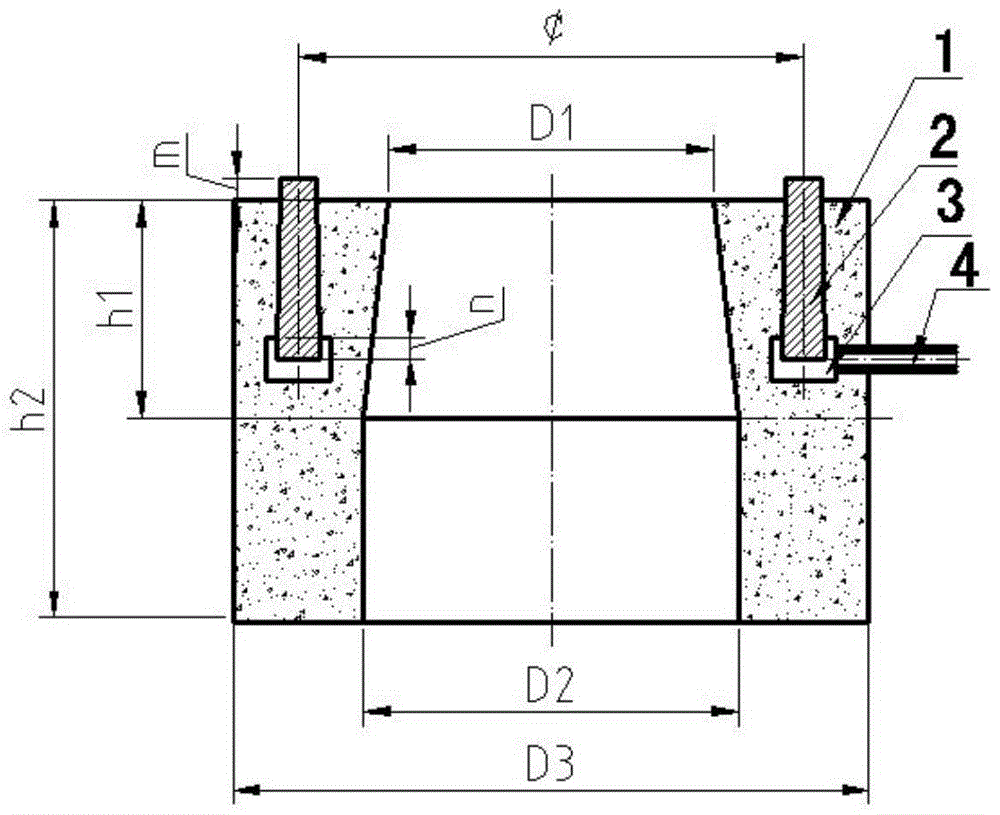
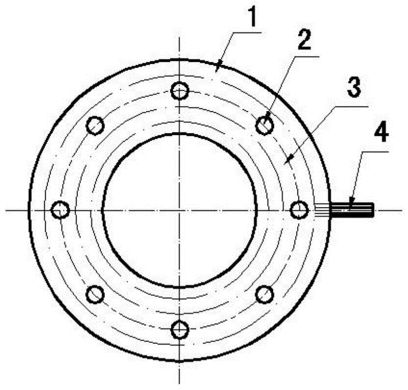
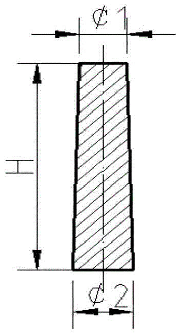
[0055] Such as figure 1 , figure 2 , image 3 , Figure 4 Shown:

[0056] A continuous casting tundish blowing argon upper nozzle block, comprising an upper nozzle block body 1, a breathable ceramic rod 2, an air chamber box 3, and an air intake pipe 4. The middle part of the upper nozzle block body 1 is provided with a vertically penetrating In the installation hole of the upper nozzle, a plurality of circular air-permeable ceramic rods 2 uniformly arranged in the body 1 of the upper nozzle block and an annular air chamber box 3 are arranged, and the air chamber box is located in the air-permeable ceramic rod. The bottom is also in communication with the breathable ceramic rod. The side of the air chamber box 3 is connected with an air intake pipe 4. One end of the air intake pipe is connected to the side of the air chamber box 3, and the other end passes through the side of the upper nozzle block body 1. It is connected with the external connecting pipe 12; it is charac...

Embodiment 2

[0067]A continuous casting tundish blowing argon upper nozzle block as described in Example 1, the difference is that the upper end of the air-permeable ceramic rod 2 protrudes from the upper surface of the upper nozzle block body 1 to a height m of 10mm, and its lower end extends into The height n into the slot 5 on the gas chamber box is 5 mm.

[0068] Diameter of the upper round table of the gas permeable ceramic rod 2¢ 1 18mm, the diameter of the lower round table ¢ 2 is 21mm, and the height H of the air-permeable ceramic rod is 100mm.

[0069] There are 16 air-permeable ceramic rods 2, which are uniformly arranged in a circular shape, and the diameter of the circular ring is ¢330mm.

[0070] The longitudinal section of the air chamber box 3 is rectangular, the width a is 35 mm, and the height b is 20 mm.

[0071] The upper nozzle block body 1 is cylindrical in shape with an outer diameter of D 3 400mm, height h 2 It is 190mm.

Embodiment 3

[0073] A continuous casting tundish blowing argon upper nozzle seat brick as described in Example 1, the difference is that the height m of the upper end of the breathable ceramic rod 2 protruding from the upper surface of the nozzle seat brick body is 15mm, and the lower end extends into the air chamber The height n in the slot 5 of the box is 10 mm.

[0074] Diameter of the upper round table of the gas permeable ceramic rod 2¢ 1 18mm, the diameter of the lower round table ¢ 2 is 20mm, and the height H of the breathable ceramic rod is 95mm.

[0075] There are 12 air-permeable ceramic rods 2, which are evenly arranged in a ring shape, and the diameter of the ring is ¢320mm.

[0076] The longitudinal section of the air chamber box 3 is rectangular, the width a is 30 mm, and the height b is 20 mm.

[0077] The upper nozzle block body 1 is cylindrical in shape with an outer diameter of D 3 380mm, height h 2 It is 203mm.


PUM

PropertyMeasurementUnit
heightaaaaaaaaaa
thicknessaaaaaaaaaa
diameteraaaaaaaaaa

Abstract

The invention relates to an upper pocket block for argon blowing of a continuous casting tundish. The upper pocket block comprises an upper pocket block body, ventilation ceramic rods, a gas chamber and a gas inlet pipe. The middle of the upper pocket block body is provided with a vertically through upper pocket mounting hole, the ventilation ceramic rods in circularly uniform arrangement and the circular gas chamber are arranged in the upper pocket block, the gas chamber is positioned at the bottoms of the ventilation ceramic rods and communicated with the ventilation ceramic rods, and the gas inlet pipe is connected to the side of the gas chamber. When argon is blown in, an annular gas curtain shield is formed around the upper pocket to perform gas washing on molten steel about to enter the upper pocket, floating and removing of slag inclusion are facilitated, the problem that slag is whirled away by eddies at the upper pocket under the low liquid level condition of the tundish is solved, and consequently cleanliness of the molten steel is improved while molten steel remained in the tundish is reduced.

Description

technical field [0001] The invention relates to a continuous casting tundish argon-blowing upper nozzle block and its installation method and application, belonging to the technical field of continuous casting technology in iron and steel metallurgy. Background technique [0002] As the metallurgical reactor between the ladle and the crystallizer, the continuous casting tundish has developed from the initial basic functions of decompression, steady flow, steel storage and flow diversion to a role of promoting The metallurgical function of floating and separating inclusions, preventing secondary oxidation of molten steel, controlling the shape of inclusions and microalloying molten steel. In recent years, continuous casting tundish air curtain retaining wall technology has been gradually popularized and applied. The principle is: use a strip-shaped air curtain retaining wall perpendicular to the flow direction of molten steel to place between the turbulence controller at the ...

Claims


Application Information

Patent Timeline
Patent Type & Authority Patents(China)
IPC IPC(8): B22D41/58B22D41/52
Inventor 武光君杜显彬殷晓霞段伦冰李霞
Owner LAIWU IRON & STEEL GRP
Learn More