Ladle breathable upper nozzle seat brick and method for controlling nozzle slag entrainment

A nozzle block and ladle technology, which is applied in the direction of manufacturing tools, casting molten material containers, metal processing equipment, etc., can solve the unsolved technical problems of eddy current slag rolling in the upper nozzle of the ladle, unreasonable design of the cavity shape of the tapping nozzle block, Can not suppress the problem of slag entanglement at the nozzle of the molten steel tank, and achieve the effect of promoting floating and removal, solving eddy current slag entanglement, and convenient and quick installation

Active Publication Date: 2016-09-21
LAIWU STEEL YINSHAN SECTION CO LTD
View PDF8 Cites 12 Cited by
  • Summary
  • Abstract
  • Description
  • Claims
  • Application Information

AI Technical Summary

Problems solved by technology

However, in the actual production process, the following problems are found: (1) The ladle has a large amount of injection, which increases the consumption and cost of steel materials; Solve the technical problem of eddy current slag entrainment in the upper nozzle of the ladle; (3) Although it can reduce the amount of slag under the ladle to a certain extent, it does not have the function of removing inclusions in molten steel and purifying molten steel
This patent has the following deficiencies: there is no ventilation element in the nozzle seat brick, there is no function of removing inclusions and purifying molten steel, and it cannot suppress the problem of slag rolling at the nozzle of the molten steel tank, and the amount of molten steel in the ladle is too much
This patent has the following disadvantages: the upper part of the breathable ceramic rod (2) is flush with the refractory body (1), the production and positioning of the breathable ceramic rod is difficult, and the product yield is low; The service life of the tapping nozzle and the nozzle block is low, which affects the life of the ladle and the consumption of refractory materials

Method used


Image

  • Ladle breathable upper nozzle seat brick and method for controlling nozzle slag entrainment
  • Ladle breathable upper nozzle seat brick and method for controlling nozzle slag entrainment
  • Ladle breathable upper nozzle seat brick and method for controlling nozzle slag entrainment

Examples


Embodiment 1

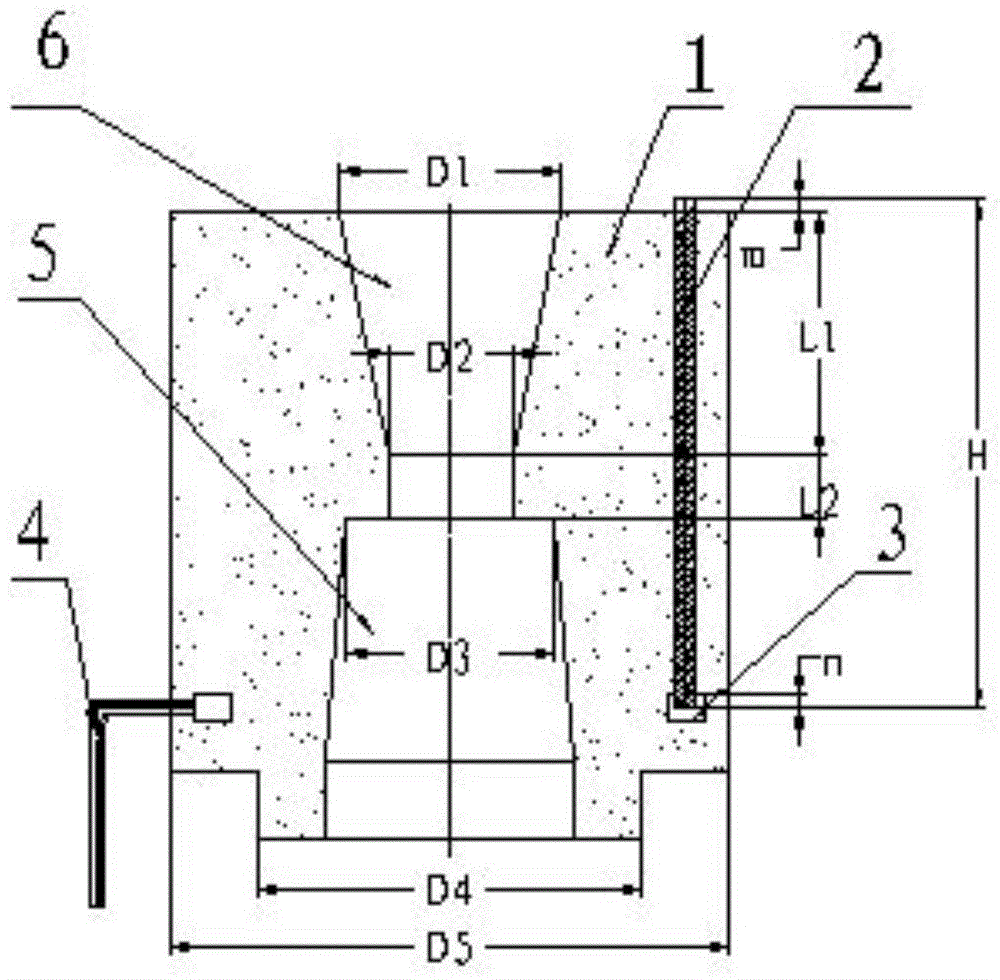
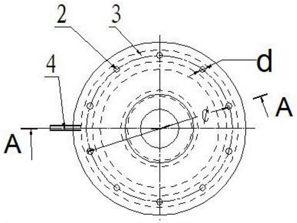
[0040] A kind of ladle breathable upper nozzle seat brick, such as Figure 1-Figure 4 As shown, it includes a ladle nozzle block body 1, a gas-permeable ceramic rod 2, an air chamber box 3. The ladle nozzle block body is provided with a flow steel hole 6, a nozzle mounting hole 5, and a ladle nozzle block from top to bottom. The brick body includes an integrally formed upper boss and a lower boss. The outer diameter of the lower boss is smaller than that of the upper boss. The upper boss of the ladle upper nozzle base brick body 1 has a cylindrical shape, and the lower boss has a cylindrical shape. The outer diameter D4 of the lower boss is smaller than the outer diameter D5 of the upper boss, the outer diameter D5 of the upper boss is 420mm, and the outer diameter D4 of the lower boss is 320mm. The air-permeable ceramic rod 2 and the air chamber box 3 are both set in the upper boss of the upper nozzle block body 1 of the ladle. The air chamber box 3 is located at the bottom of...

Embodiment 2

[0046] The ladle air-permeable upper nozzle block as described in Example 1, the difference is:

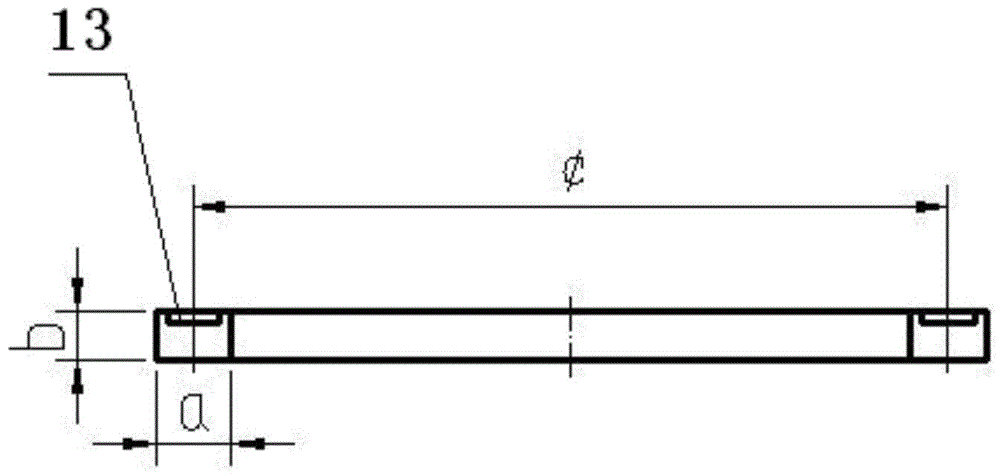
[0047] The outer diameter D5 of the upper boss of the ladle upper nozzle base brick body 1 is 480mm, and the outer diameter D4 of the lower boss is 360mm. The diameter d of the air-permeable ceramic rod 2 is 12mm, the height of the air-permeable ceramic rod is greater than the height of the flow steel hole and less than the height of the boss on the brick body of the ladle upper nozzle, and the height H of the air-permeable ceramic rod is 320mm. There are 16 air-permeable ceramic rods 2, which are uniformly arranged in the upper nozzle block body in a ring shape around the flow steel hole, and the diameter of the ring is 400mm. The top end of the air-permeable ceramic rod 2 protrudes from the upper surface of the upper nozzle base brick body to a height m of 10mm. The air chamber box is provided with 16 slots for fixing the air-permeable ceramic rod. The shape and position of the slo...

Embodiment 3

[0051] The ladle air-permeable upper nozzle block as described in Example 1, the difference is:

[0052] The outer diameter D5 of the upper boss of the ladle upper nozzle base brick body 1 is 460mm, and the outer diameter D4 of the lower boss is 340mm. The diameter d of the air-permeable ceramic rod 2 is 18mm. The height of the air-permeable ceramic rod is greater than the height of the flow steel hole and less than the height of the boss on the brick body of the ladle upper nozzle. The height of the air-permeable ceramic rod H is 360mm. There are 12 air-permeable ceramic rods, which are uniformly arranged in the upper nozzle base brick body in a ring shape around the flow steel hole. The diameter of the ring is 360mm. The height m of the top end of the ventilating ceramic rod 2 protruding from the upper surface of the upper nozzle block body is 6mm. The air chamber box is provided with 12 slots for fixing the ventilating ceramic rods. The shape and position of the slots correspo...


PUM

PropertyMeasurementUnit
diameteraaaaaaaaaa
flame retardantaaaaaaaaaa
densityaaaaaaaaaa

Abstract

The invention relates to a ladle ventilating upper nozzle seat brick and a method for controlling nozzle slag volume, which comprises a ladle upper nozzle seat brick body, a ventilating ceramic rod and an air chamber box, the air chamber box is located at the bottom of the ventilating ceramic rod and connected with the ventilating ceramic rod Connected, there are a plurality of breathable ceramic rods, which are evenly arranged in the body of the upper nozzle block in a ring around the flow steel hole. The top of each breathable ceramic rod protrudes from the upper surface of the upper nozzle block body. A plurality of slots for fixing the air-permeable ceramic rods are provided, and the bottom end of each air-permeable ceramic rod extends into the slot of the air intake chamber box. When the molten steel in the ladle is at a low level, argon gas is blown in from the inlet pipe to form a ring-shaped air curtain barrier around the upper nozzle of the ladle to wash the molten steel that is about to enter the upper nozzle. The problem of eddy current slag entrainment at the nozzle not only improves the cleanliness of molten steel, but also reduces the amount of molten steel in the ladle injection surplus, a year-on-year decrease of more than 30%.

Description

Technical field [0001] The invention relates to a ladle air-permeable upper nozzle seat brick and a method for controlling slag entrapment at the nozzle, and belongs to the technical field of steelmaking in iron and steel metallurgy. Background technique [0002] In the production of the continuous caster, as the level of the molten steel in the ladle decreases, the molten steel is prone to eddy currents at the nozzle of the ladle, so that the slag on the surface of the molten steel is caught in and enters the tundish of the continuous caster, resulting in increased inclusions. Initiate slab quality defects. At present, the ladle slag detection technology is usually used to reduce the amount of slag under the ladle. The main methods for detecting the slag under the ladle are: the method of detecting the slag of the ladle based on the infrared principle, the method of detecting the slag of the ladle based on the electromagnetic coil and the method of detecting the slag based on th...

Claims


Application Information

Patent Timeline
Patent Type & Authority Patents(China)
IPC IPC(8): B22D41/50
Inventor 武光君王中学
Owner LAIWU STEEL YINSHAN SECTION CO LTD
Why Eureka
Try Eureka