

Left viewing device for automobile
A technology for automobiles and flat mirrors, applied in optical observation devices, vehicle parts, transportation and packaging, etc., can solve the problems of not being able to observe the situation of vehicles coming from the left, unsatisfactory conditions, traffic accidents, etc., and achieve good viewing distance and simple structure , Ease of use
Inactive Publication Date: 2014-09-10
罗威
View PDF1 Cites 0 Cited by
- Summary
- Abstract
- Description
- Claims
- Application Information
AI Technical Summary
Problems solved by technology
[0002] At present, we know that the B-pillar of a car blocks the sight of the driver turning left and turning around, thus often causing traffic accidents. For example, the multi-view mirror of a car with the patent No. 201020135902.3 can only observe the rear, but not the left The car situation is not ideal
Method used
View moreImage
Smart ImageViewing Examples

Examples
Embodiment Construction
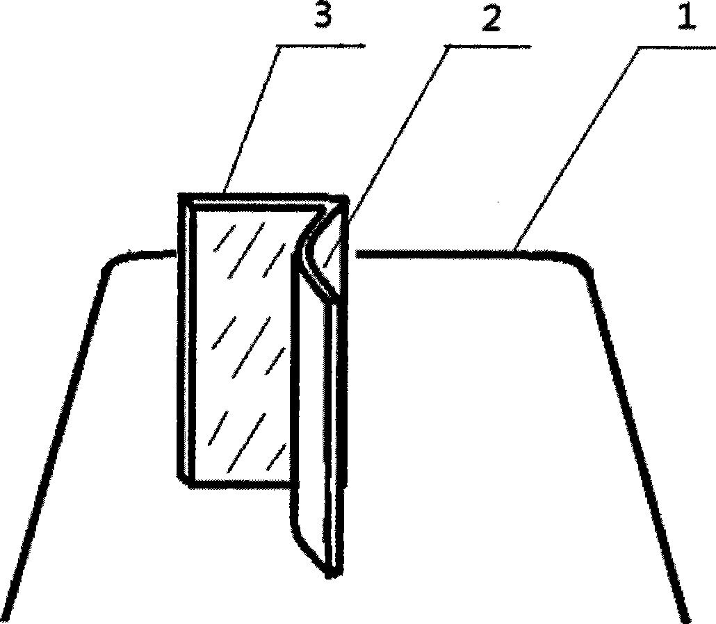
[0009] figure 1 Among them, a plane mirror 3 facing the driver is set at the left front of the car engine cover 1, and a convex mirror 2 facing the left is arranged on the right side of the plane mirror. During use, the present invention is installed in the middle position of the left half of the car engine cover, and is properly adjusted until the driver can see the car coming from the left side, so as to prepare for deceleration and parking.
Login to View More PUM
 Abstract
The invention relates to the technical field of reflective mirrors. A left viewing device for an automobile consists of a plane mirror and a convex mirror and is characterized in that the plane mirror over against a driver is arranged at the left front part of a bonnet of the automobile, and the convex mirror over against the left direction is arranged on the right side of the plane mirror. While in use, the left viewing device disclosed by the invention is mounted in the middle of the left-half part of the bonnet of the automobile and is adjusted appropriately until the driver can see a car coming from the left side, so that the driver prepares for deceleration and parking. The left viewing device has the beneficial effects that the structure is simple, the left viewing device is convenient to use, sight distances are good, and the effect for preventing accidents from occurring is good.
Description
technical field [0001] The invention relates to the technical field of reflective mirrors. Background technique [0002] At present, we know that the B-pillar of a car blocks the sight of the driver turning left and turning around, thus often causing traffic accidents. For example, the multi-view mirror of a car with the patent No. 201020135902.3 can only observe the rear, but not the left The car situation is not ideal. Contents of the invention [0003] In order to overcome above-mentioned deficiency, the present invention provides a kind of car left-viewing device, just can reach the purpose of avoiding traffic accident. [0004] The technical solution of the present invention to solve its technical problems is: a car view left device composed of a plane mirror and a convex mirror, characterized in that: a plane mirror facing the driver is set on the left front of the car engine cover, and a plane mirror facing the driver is arranged on the right side of the plane mirr...
Claims
Login to View More Application Information
Patent Timeline
 Patent Type & AuthorityApplications(China)
IPC IPC(8): B60R1/00
Inventor罗威
Owner罗威