Superconducting magnet low-temperature container conveying and supporting device

A support device and low-temperature container technology, applied in the direction of external accessories, etc., can solve the problems that high vacuum is not easy to maintain for a long time, increases the difficulty of work, and affects vacuum performance, etc.

Active Publication Date: 2014-09-10
INST OF ELECTRICAL ENG CHINESE ACAD OF SCI
View PDF6 Cites 2 Cited by
  • Summary
  • Abstract
  • Description
  • Claims
  • Application Information

AI Technical Summary

Problems solved by technology

Since opening holes on the bottom plate of the vacuum container affects the vacuum seal, a solution is to return the superconducting magnet cryogenic container to room temperature, break the vacuum to return the pressure in the vacuum container to atmospheric pressure, and then install the transport support device, which requires Re-evacuating and cooling the superconducting magnet cryogenic container is not only time-consuming and labor-intensive but also increases the difficulty of work; another solution is to set a movable sealing device at the opening, and pass the transport support rod through the movable sealing device of the vacuum container in advance. but not inserted into the bottom plate of the inner container, so that the transportation support rod can be continuously pushed and inserted into the bottom plate of the inner container without breaking the vacuum during transportation, but in fact the transportation support rod and the seal in the movable sealing device are movable Sealing, high vacuum is not easy to maintain for a long time, and repeated operations often make the seal invalid and affect the vacuum performance

Method used


Image

  • Superconducting magnet low-temperature container conveying and supporting device
  • Superconducting magnet low-temperature container conveying and supporting device
  • Superconducting magnet low-temperature container conveying and supporting device

Examples


Embodiment Construction

[0019] The present invention will be further described below in conjunction with the accompanying drawings and specific embodiments.

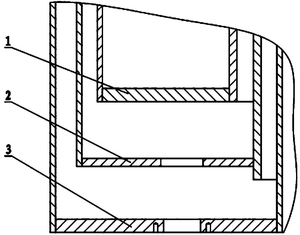
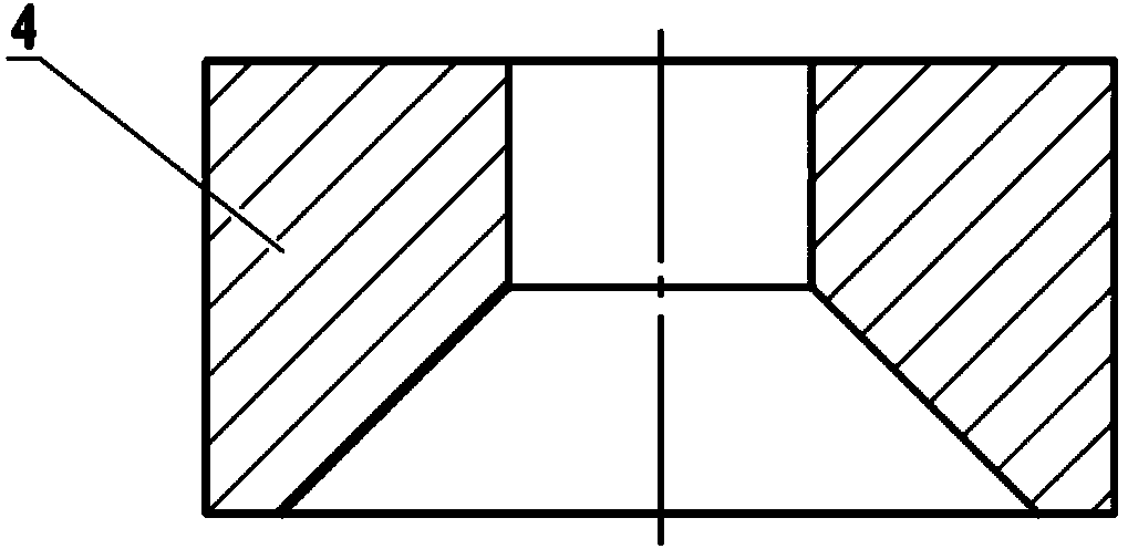
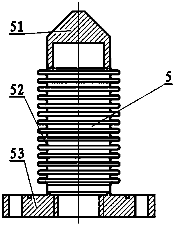
[0020] The transportation supporting device of the superconducting magnet cryogenic container of the present invention comprises an inner container bottom plate 1 , a cold shield bottom plate 2 and a vacuum container bottom plate 3 , an inner container transport support 4 , a bellows sealing seat 5 and a push rod 6 . The transport support 4 of the inner container, the sealing seat 5 of the bellows and the ejector rod 6 are coaxial.

[0021] Such as figure 1 As shown, the inner container bottom plate 1, the cold shield bottom plate 2, and the vacuum container bottom plate 3 of the present invention are arranged in parallel from inside to outside, and a superconducting magnet low-temperature container transportation support device is reserved on the cold shield bottom plate 2 and the vacuum container bottom plate 3 the mounting holes.

[0022] ...


PUM


Abstract

A superconducting magnet low-temperature container conveying and supporting device comprises an inner container conveying support (4), a corrugated pipe sealing base (5) and an ejector rod (6). A taper hole is formed in the lower end of an inner cavity of the inner container conveying support (4). The corrugated pipe sealing base (5) comprises a tapered base (51), a corrugated pipe (52) and a sealing flange (53). The tapered base (51) is divided into a tapered section and a circular section. A taper angle of the taper section is the same as a taper angle of the taper hole of the inner cavity of the inner container conveying support (4). A circular hole is formed in the bottom of the circular section and used for containing the ejector rod. The inner container conveying support (4) is welded to an inner container bottom plate (1). The corrugated pipe sealing base (5) is fixed to a vacuum container bottom plate (3) through the sealing flange (53). The ejector rod (6) is rotationally inserted into the tapered base (51) and pushes the corrugated pipe sealing base (5) to move until the tapered base (51) is inserted into the taper hole in the inner cavity of the inner container conveying support (4) to make close contact with the taper hole.

Description

technical field [0001] The invention relates to a transport supporting device for a cryogenic container, in particular to a transport supporting device for a superconducting magnet cryogenic container. Background technique [0002] The superconducting magnet cryogenic container includes an inner container, a cold shield and a vacuum container from the inside to the outside. The superconducting magnet is fixed inside the inner container, and the inside of the vacuum container maintains a high vacuum. In order to minimize the heat transfer from the outside through the tie rod device, the inner container and the cold screen are fixed on the vacuum container with a tie rod device with a cross-section as small as possible, so that the bearing capacity of the tie rod is limited, especially for the inner container loaded with superconducting magnets. , due to strict requirements on heat transfer, the bearing capacity margin of the tie rod is more limited. Due to actual needs, supe...

Claims


Application Information

Patent Timeline
Patent Type & Authority Applications(China)
IPC IPC(8): B65D25/20
Inventor 昌锟王晖赵保志陈顺中李献王秋良
Owner INST OF ELECTRICAL ENG CHINESE ACAD OF SCI
Why Eureka
Try Eureka