Flat knitting machine with movable sinker

A sinker and flat knitting machine technology, applied in weft knitting, textiles, papermaking, knitting, etc., can solve problems such as large stress

Active Publication Date: 2016-02-24
SHIMA SEIKI MFG LTD
View PDF12 Cites 0 Cited by
  • Summary
  • Abstract
  • Description
  • Claims
  • Application Information

AI Technical Summary

Problems solved by technology

The torsion spring has the following possibility: If a large downward thrust is to be obtained in the closed state of the sinker, the stress is too large in the open state of the sinker.

Method used


Image

  • Flat knitting machine with movable sinker
  • Flat knitting machine with movable sinker
  • Flat knitting machine with movable sinker

Examples


Embodiment 1

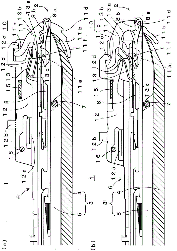
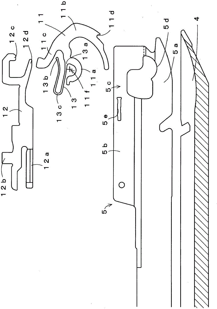
[0050] figure 1 A schematic structure and operation of a flat knitting machine 1 provided with a movable sinker 10 as Embodiment 1 are shown, figure 1 (a) represents the closed state, figure 1 (b) represents the open state. The flatbed knitting machine 1 knits a knitted fabric on the needle bed 2 side, and needle plates 5 are arranged side by side on a base 4 to form a needle bed 3 . Needle grooves 6 are formed between needle plates 5 juxtaposed at a constant pitch in a direction perpendicular to the paper surface. The base 4 and the needle plate 5 are positioned by the metal wire 7 penetrating in the direction perpendicular to the paper surface. The knitting needles 8 are accommodated in each needle groove 6 . The knitting needle 8 shown in the figure is a compound needle that opens and closes the hook provided at the front end of the needle body 8a on the tooth mouth 2 side by a tongue portion (tang) arranged at the front end of the needle mouth 2 side of the slider 8b, ...

Embodiment 2

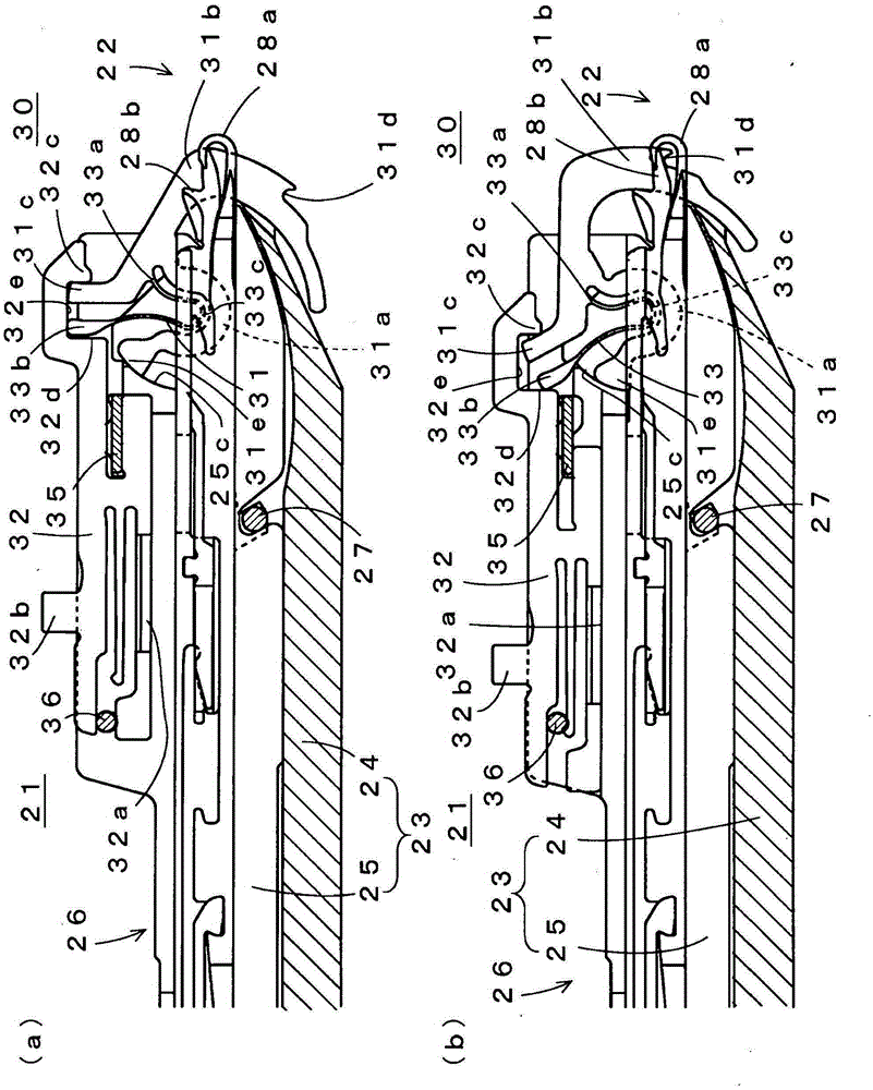
[0063] image 3 In Example 2, image 3 (a) The schematic structure and operation of the flat knitting machine 21 provided with the movable sinker 30 are shown in a closed state, image 3 (b) The schematic structure and operation|movement of the flatbed knitting machine 21 provided with the movable sinker 30 are shown in an open state. In this embodiment, although the bent portion 33c of the torsion spring 33 is accommodated inside the support portion 31a of the sinker 31, the other end 33b side of the torsion spring 33 is pushed by the passive arm 31c of the sinker 31 and the sinker. The action position of the front end portion 32c of the piece 32 is capable of pressing in the closed state from the pressing portion 32d on the side in the direction away from the tooth gap 22 . That is, near the front end of the sinker jack 32, one recess 32e opening downward is formed following the front end portion 32c. The recess 32e is formed such that the distance between the front end p...

Embodiment 3

[0068] Figure 5 In, as Example 3, Figure 5 (a) The schematic structure and operation of the flat knitting machine 41 provided with the movable sinker 50 are shown in a closed state, Figure 5 (b) The schematic structure and operation|movement of the flat knitting machine 41 provided with the movable sinker 50 are shown in an open state. In this embodiment, the swing of the sinker 51 is also supported by an upper support portion 51g and a lower support portion 51a corresponding to the support portion 11a of the first embodiment. Since the upper support portion 51g is provided, no space can be provided inside the lower support portion 51a, and the one end 53a side of the torsion spring 53 branches from the lower support portion 51a at a position in a direction away from the tooth gap 42 than the upper support portion 51g. The action arm 51b and the passive arm 51c are branched from the position in the direction close to the tooth gap 42 in the lower support portion 51a.

[...


PUM


Abstract

[Problem to be solved] To provide a flatbed knitting machine equipped with the movable sinkers, each of which is capable of moderating shape restriction for a torque spring and a sinker even when stresses of the torque spring is prevented from being too large in a sinker opened state, for a part of the movable sinker receiving actions from a sinker jack. [Solution] A passive arm 11c of a sinker 11 diverges from a portion between a support receive part 11a and a function arm 11b. Even when a sinker jack 12 is made to retreat in the direction of being apart from a needle bed gap 2 and the sinker 11 is made into an opened state, a suppressing pressure from a suppressing part 12d to the other end 13b of the torque spring is weakened, so that a stress of the torque spring can be prevented from being too large in the opened state of the sinker 11. The suppressing part 12d and the leading edge part 12c of the sinker jack 12 need not be made closer to each other and restriction for shapes of the sinker 11 and the torque spring 13 can be moderated.

Description

technical field [0001] The present invention relates to a flat knitting machine equipped with a movable sinker which can be opened and closed and can push down a knitted fabric in the closed state. Background technique [0002] Conventionally, in a flat knitting machine, a technique is known in which a sinker forming a stitch together with knitting needles in a needle bed is movable and can be opened and closed (see, for example, Patent Documents 1 and 2). The movable sinker has a support part supported in a swingable manner near the tooth bed of the needle bed, an active arm extending from the support part toward the direction close to the tooth bed, and a passive arm extending from the support part in a direction away from the tooth bed. arm. The support portion is arc-shaped, and is fitted with an arc-shaped recessed support portion provided on the needle bed side, and the center of the arc serves as a virtual swing fulcrum. The movable sinker is further provided with a...

Claims


Application Information

Patent Timeline
Patent Type & Authority Patents(China)
IPC IPC(8): D04B15/06
CPCD04B15/06D04B15/70D04B15/90
Inventor 园村稔
Owner SHIMA SEIKI MFG LTD
Why Eureka
Try Eureka