Tubular ventilation device, control method thereof and air conditioner which uses tubular ventilation device

A technology for ventilation devices and cross-flow fans, which is applied in heating and ventilation control systems, airflow control components, ventilation systems, etc., and can solve problems such as irreversible air inlet and outlet

Active Publication Date: 2014-09-10
GREE ELECTRIC APPLIANCES INC
View PDF10 Cites 10 Cited by
  • Summary
  • Abstract
  • Description
  • Claims
  • Application Information

AI Technical Summary

Problems solved by technology

[0003] The invention provides a cross-flow ventilation device with interchangeable air inlet and

Method used


Image

  • Tubular ventilation device, control method thereof and air conditioner which uses tubular ventilation device
  • Tubular ventilation device, control method thereof and air conditioner which uses tubular ventilation device
  • Tubular ventilation device, control method thereof and air conditioner which uses tubular ventilation device

Examples


Embodiment 1

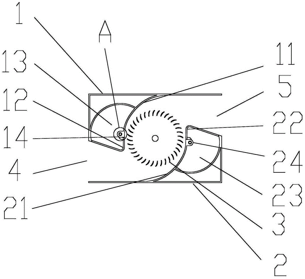
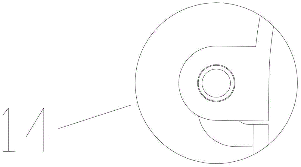
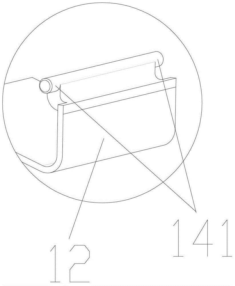
[0024] See figure 1 , the cross-flow ventilation device of the present embodiment includes an outer casing and a cross-flow fan 3 disposed in the outer casing, the outer casing includes a first casing 1 and a second casing 2, and the first casing 1 and the second casing The body 2 encloses a first vent 4 and a second vent 5 respectively. The first housing 1 includes a first volute 11, a first volute tongue 12, and a first volute tongue adjustment groove 13; the second housing 2 includes a second volute 21, a second volute tongue 22, a second Worm tongue adjustment groove 23. The first volute 11 is movably connected with the first volute tongue 12, so that the first volute tongue 12 has a working position and a hidden reversing position by moving along the first volute tongue adjustment groove 13; the second volute 21 and the second volute tongue 22 are movably connected, so that the second volute tongue 22 has a working position, and the hidden waiting for moving along the s...

Embodiment 2

[0034] Compared with the first embodiment, this embodiment is mainly different in the movable connection mode of the volute case and the volute tongue, and other components or structures are common, so no more details are given here.

[0035] In this embodiment, the first volute 11 and the first volute tongue 12 are movably connected through a first sliding assembly; the second volute 21 and the second volute tongue 22 are movably connected through a second sliding assembly. The first sliding assembly includes a first sliding groove provided on the first volute 11 and a first sliding block arranged on the first volute tongue 12, and the sliding block is matched with the sliding groove. By driving the first slider to move on the first chute, the first volute tongue 12 moves to the working position or the waiting position; and drives the second sliding assembly in the same way, so that the second volute tongue 22 moves to the waiting position correspondingly Or the working posit...

Embodiment 3

[0038] In order to further increase the scope of application of the cross-flow ventilation device, this technical solution can also be applied to a cross-flow ventilation device with more than two ventilation openings.

[0039] In this embodiment, each ventilation port needs to be provided with a volute tongue and a volute that are flexibly connected. By controlling part of the volute tongue to be in the waiting position and the other part of the volute tongue to be in the working position in a targeted manner, to meet the requirements for entering and exiting. Air volume requirements and / or different requirements for inlet and outlet locations.


PUM


Abstract

The invention discloses a tubular ventilation device for solving the problems that due to particularity of structure of an air flue, air can enter an existing tubular ventilation device only through an air vent, and flows out from the other air vent, and accordingly limitation exists in the existing tubular ventilation device during the practical application process, and the existing tubular ventilation device can not be used in a site where the airflow direction needs to be reversed. The tubular ventilation device is formed by arranging a plurality of movable worm tongues on the existing tubular ventilation device, and the tubular ventilation device can be switched into a work position or a wait position according to actual needs, and solves the above problems, and furthermore multidirectional ventilation of the tubular ventilation device is achieved.

Description

technical field [0001] The invention relates to a cross-flow ventilation device, in particular to a cross-flow ventilation device which can reverse the direction of air inlet and outlet. Background technique [0002] Due to the particularity of the air duct structure, the volute tongue structure of the volute needs to be designed on the air outlet side of the air outlet, while the volute tongue structure cannot exist on the air inlet side of the air inlet. Therefore, the cross-flow ventilation devices in the prior art can only take in the air from one fixed vent and output the air from another fixed vent, which makes the cross-flow ventilation devices have limitations in practical application and cannot be used. In places where the direction of air flow needs to be reversed. Contents of the invention [0003] The invention provides a cross-flow ventilation device in which an air inlet and an air outlet can be switched to each other, which solves the technical problem that...

Claims


Application Information

Patent Timeline
IPC IPC(8): F24F7/007F24F13/10F24F11/00
CPCY02B30/70
Inventor 骆海王现林
Owner GREE ELECTRIC APPLIANCES INC
Why Eureka
Try Eureka