Multifunctional grinding machine and working method thereof

A working method and multi-functional technology, applied in the direction of grinding machine, grinding bed, grinding machine parts, etc., can solve the problems of reducing grinding efficiency, large fixed investment for putting green machine users, increasing production cost, etc., to achieve Moving and Stationary Effects

Active Publication Date: 2015-11-11
XINGHUA TAILIN MASCH CO LTD
View PDF5 Cites 5 Cited by
  • Summary
  • Abstract
  • Description
  • Claims
  • Application Information

AI Technical Summary

Problems solved by technology

[0002] During the use of the green machine, the wear of the hob and bedknife is a normal phenomenon, and it is necessary to regrind the hob and bedknife from time to time, because the hob sharpening mainly includes hob outer circle sharpening and hob Grinding, while the hob is a spiral cutting edge distributed on the cylindrical surface, which is usually difficult to grind. It needs to be equipped with special grinding equipment hob grinder and hob automatic chamfering grinder. Grinding machine, so the grinding of the green machine tool needs to use three special grinding machines, which brings a large fixed investment to the user of the green machine, and the user's operation is inconvenient, which increases the production cost and reduces the grinding efficiency. This is what needs to be resolved

Method used


Image

  • Multifunctional grinding machine and working method thereof
  • Multifunctional grinding machine and working method thereof
  • Multifunctional grinding machine and working method thereof

Examples


Embodiment 1

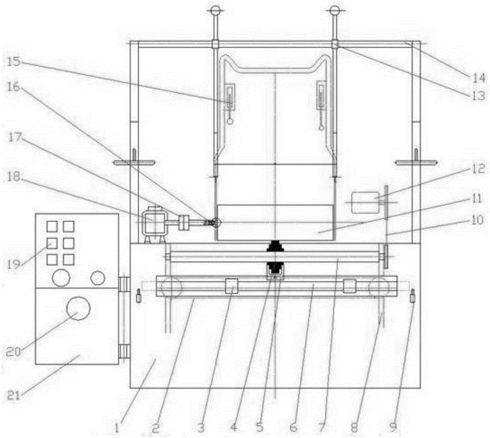
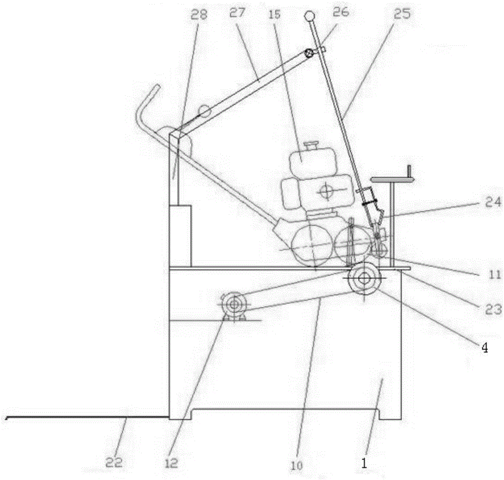
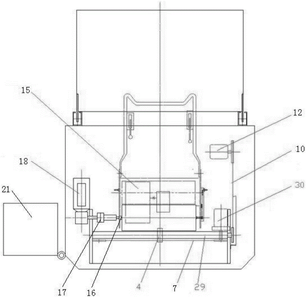
[0039] further as Figure 4 to Figure 21 As shown, to grind the outer circle of the hob of the putting green machine, first put the putting green machine 15 on the lifting platform 22 during operation, then lift the putting green machine 15 onto the bed panel 23 through the lifting mechanism, and use the clamping frame 24 Clamp the fixed ends on the left and right sides of the front end of the putting green machine, and then adjust the position of the putting green machine by adjusting the angle between the second clamping rod fixing sleeve 26 and the clamping frame crossbeam 14 and the length of the clamping rod 25 protruding out. One end of the sleeve shaft 16 is inserted into the output shaft of the hob 11 of the green machine 15, and the other end is connected with the coupling 17. After all adjustments are made, all bolts are locked, and finally the green machine 15 is fixed on the grinder; After the first reduction motor 18 is started, it drives the forward rotation of t...

Embodiment 2

[0041] further as Figure 4 to Figure 21 As shown, the hob of the putting green machine is automatically chamfered. During operation, the putting green machine 15 is first placed on the lifting table 22, and then the putting green machine 15 is lifted onto the bed panel 23 by the lifting mechanism, and clamped with the clamping frame 24. Hold the fixed ends on the left and right sides of the front end of the putting green machine, and then adjust the position of the putting green machine by adjusting the angle between the second clamping rod fixing sleeve 26 and the clamping frame crossbeam 14 and the length of the clamping rod 25 protruding out. One end of the cylinder shaft 16 is inserted into the output shaft of the hob 11 of the green machine 15, and the other end is connected with the coupling 17. After all adjustments are made, all bolts are locked, and finally the green machine 15 is fixed on the grinder; A motor 54 drives the linear bearing 58 to move laterally on the ...

Embodiment 3

[0043] further as Figure 4 to Figure 21 As shown, the bottom knife of the putting green machine is ground. During the operation, first put the putting green machine 15 on the lifting platform 22, then lift the putting green machine 15 onto the bed panel 23 through the lifting mechanism, and use the clamping frame 24 clamp the fixed ends on the left and right sides of the front end of the putting green machine, and then adjust the position of the putting green machine by adjusting the angle between the second clamping rod fixing sleeve 26 and the clamping frame crossbeam 14 and the length of the clamping rod 25 protruding out, and at the same time Insert one end of the sleeve shaft 16 into the output shaft of the hob 11 of the green machine 15, and connect the other end with the coupling 17. After all adjustments are made, all bolts are locked, and finally the green machine 15 is fixed on the grinder; After the second motor 78 is turned on, the lateral movement of the outer ci...


PUM


Abstract

The invention belongs to the technical field of application of grinding machines for rolling cutters of green putting machines, and particularly discloses a multifunctional grinding machine. The multifunctional grinding machine is composed of a rolling-cutter-outer-circle grinding machine body, an accessory A and an accessory B. The rolling-cutter-outer-circle grinding machine body is composed of a machine main body, a main transmission mechanism, a driving mechanism, a grinding-wheel-frame linear movement mechanism, a clamping mechanism and a control mechanism. According to the multifunctional grinding machine, the three functions are achieved, the machine main body and a transmission system are shared, and the three functions of grinding the outer circles of rolling cutters, grinding the chamfers of the rolling cutters and grinding bottom cutters are achieved; the accessory A and the accessory B are integrally manufactured to independently achieve one function; in addition, an aviation plug is independently connected to the accessory A and the accessory B, and after the aviation plug is inserted into a jack in a control cabinet, backward rotation of gear motors is achieved besides rotation of motors on the accessories; due to a special house-shaped bracket structure, reciprocating linear movement of grinding wheels is achieved through forward rotation and backward rotation of a chain transmission part; meanwhile, due to a special U-shaped plate structure, power of the machine is transmitted to the accessories, and power for the transverse movement of the motors on the accessories is given.

Description

technical field [0001] The invention belongs to the application technical field of hob grinders for putting green machines, and specifically relates to a multifunctional grinder and a working method thereof. Three grinders, a hob cylindrical grinder, a hob automatic chamfering grinder and a bottom knife grinder, are combined into one grinder. Realize the grinding operation of three kinds of grinding machines. Background technique [0002] During the use of the green machine, the wear of the hob and bedknife is a normal phenomenon, and it is necessary to regrind the hob and bedknife from time to time, because the hob sharpening mainly includes hob outer circle sharpening and hob Grinding, while the hob is a spiral cutting edge distributed on the cylindrical surface, which is usually difficult to grind. It needs to be equipped with special grinding equipment hob grinder and hob automatic chamfering grinder. Grinding machine, so the grinding of the green machine tool needs to ...

Claims


Application Information

Patent Timeline
Patent Type & Authority Applications(China)
IPC IPC(8): B24B3/12B24B3/36B24B9/04B24B27/00B24B41/02B24B47/16B24B47/04
CPCB24B3/12B24B3/36B24B9/04B24B27/0076B24B41/02B24B47/04B24B47/16
Inventor 刘跃周忠旺
Owner XINGHUA TAILIN MASCH CO LTD
Why Eureka
Try Eureka