

Intelligent safety lock for gun
A technology for safety locks and guns, applied in the field of gun locks, can solve the problems of user danger, time-consuming, complicated unlocking operations of trigger locks, etc., and achieve the effects of fast unlocking speed, stable structure, and automatic and fast locking.
- Summary
- Abstract
- Description
- Claims
- Application Information
AI Technical Summary
Problems solved by technology
Method used
Image

Examples
Embodiment 1
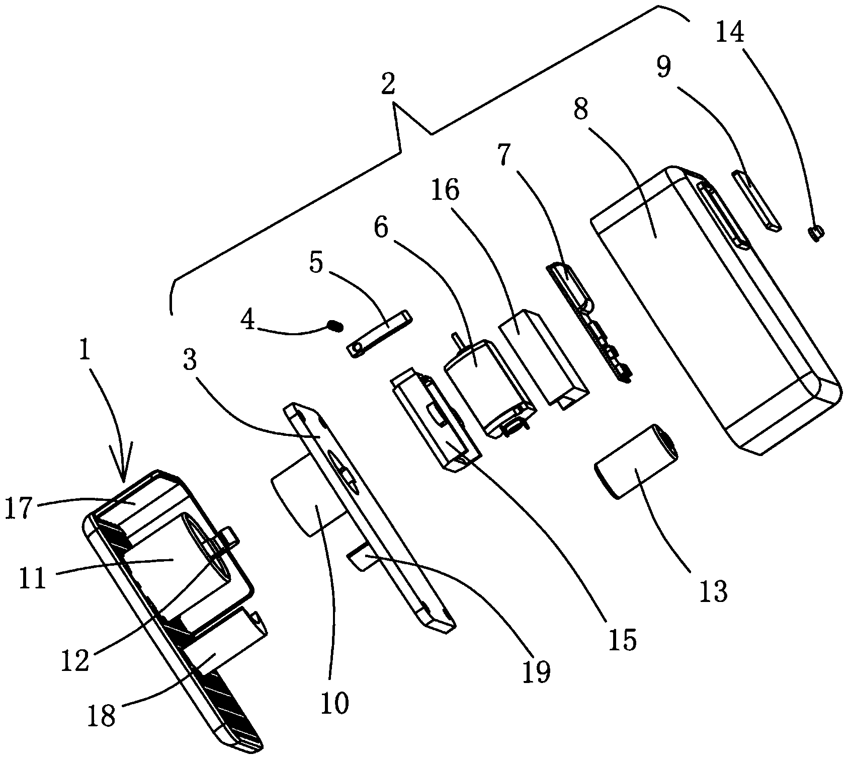
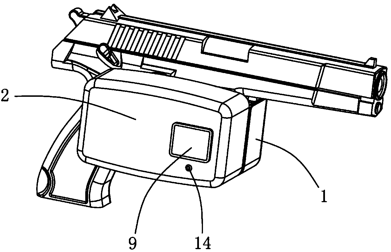
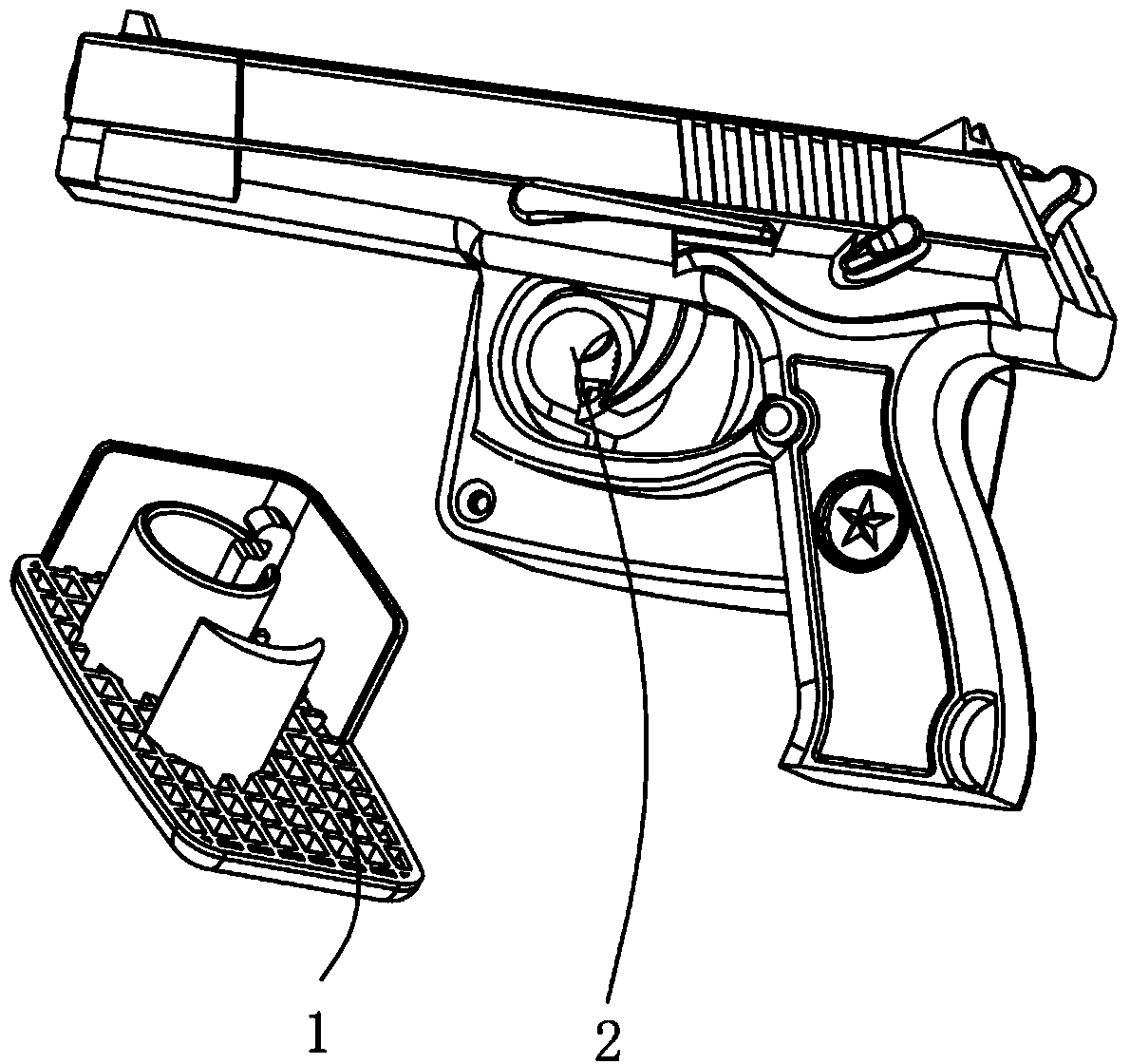
[0029] Example 1, see Figure 1 to Figure 3 Shown:
[0030] An intelligent safety lock for guns comprises a left lock base 1 and a right lock base 2 which are interlocked with each other. After the left lock base 1 and the right lock base 2 are locked together, they can be fixedly clamped at the trigger position of the gun. It should be noted that the left and right directions of the left lock base 1 and the right lock base 2 can be interchanged according to the actual situation of the gun.
[0031] The right lock base 2 includes a lock frame 3, a spring 4, a lock catch 5, a motor 6, a fingerprint intelligent processing module 7, a lock base housing 8, a fingerprint collection board 9 and an indicator light 14, and the fingerprint collection board 9 and an indicator light 14 Located on the outside of the lock base housing 8, the fingerprint collection board 9 is used to obtain fingerprint information, and the indicator light 14 is used to indicate the working status of the fi...
Embodiment 2
[0034] Example 2, see Figure 4 to Figure 5 Shown:
[0035] The difference between the gun intelligent safety lock described in this embodiment and Embodiment 1 is that the structure of the locking mechanism is different. The locking mechanism of this embodiment includes a rotor 21 connected to the output shaft of the motor 6, a rotor 21 located on the right lock The lock catch 5 torsion spring 20 on the seat 2, the middle part of the lock catch 5 is arranged on the right lock seat 2 through the shaft post, and the lock catch 5 can be limited around the shaft post by two spacer posts located on the right lock seat 2. At the same time, the torsion spring 20 is sleeved on the shaft, so that the lock catch 5 remains in the locked position, and the contact end surface of the lock tongue 12 and the lock catch 5 is an inclined plane, so the motor 6 does not need to drive the lock catch 5 to rotate to open position, the lock tongue 12 can be directly inserted, and the lock tongue 12...
Embodiment 3
[0036] Example 3, see Figure 6 to Figure 7 Shown:
[0037] The difference between the gun intelligent safety lock described in this embodiment and Embodiment 1 is that the structure of the locking mechanism is different. The locking mechanism of this embodiment includes a driving gear 22 connected to the output shaft of the motor 6, located on the right On the lock base 2, the driven gear 23 meshed with the driving gear, the snap close 5 fixedly connected with the rotating shaft of the driven gear 23, the spring 4 located on the right lock base 2, the right lock base 2 is provided with a limit post, The positioning column and the spring 4 are respectively located on both sides of the lock catch 5, and the lock catch 5 is offset against the limit post under the elastic force of the spring 4, so that the lock catch 5 remains in the locked position, and the contact between the dead bolt 12 and the lock catch 5 The end face is fitted with an inclined plane, so the motor 6 can di...
PUM
 Abstract
Description
Claims
Application Information