
Method for measuring residual stress of pyrolytic carbon coating by virtue of X ray diffraction

A technique of residual stress, X-ray, applied in the direction of material analysis using radiation diffraction, etc.

Inactive Publication Date: 2014-09-10
HANGZHOU DIANZI UNIV
View PDF5 Cites 11 Cited by
  • Summary
  • Abstract
  • Description
  • Claims
  • Application Information

AI Technical Summary

Problems solved by technology

At present, there is no complete technical solution for measuring the residual stress of pyrolytic carbon by X-ray diffraction method

Method used


Image

  • Method for measuring residual stress of pyrolytic carbon coating by virtue of X ray diffraction
  • Method for measuring residual stress of pyrolytic carbon coating by virtue of X ray diffraction
  • Method for measuring residual stress of pyrolytic carbon coating by virtue of X ray diffraction

Examples


Embodiment Construction

[0015] The present invention will be further described below in conjunction with the accompanying drawings and embodiments.

[0016] A method for X-ray diffraction measurement of pyrolytic carbon coating residual stress, the specific steps are as follows:

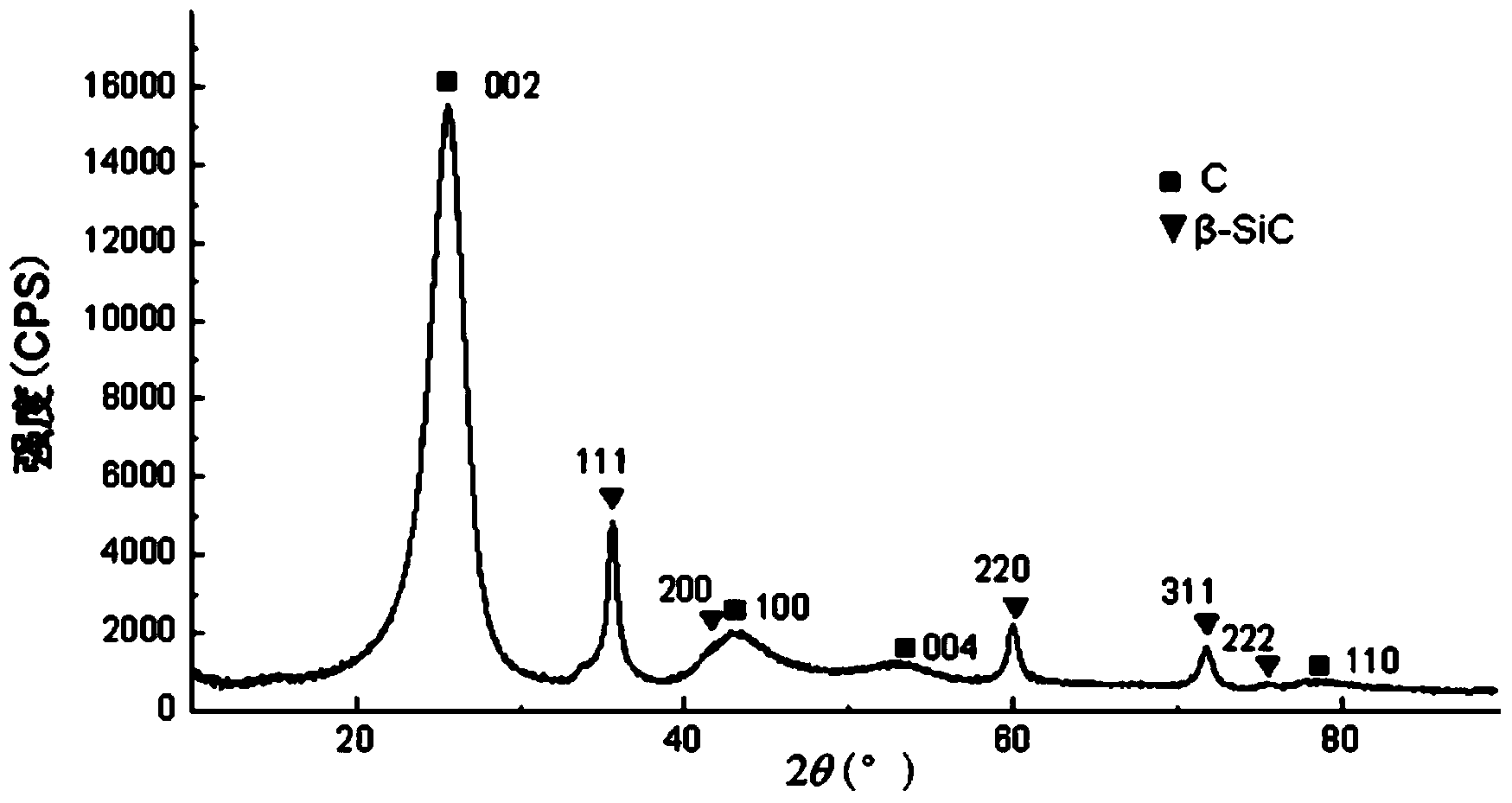
[0017] Step 1. Select the pyrolytic carbon coating material deposited on the graphite substrate prepared by the fluidized bed chemical vapor deposition process as an experimental sample, and carry out routine X-ray detection on the experimental sample to obtain a full spectrum of diffraction, such as figure 1 As shown, the maximum diffraction angle 2θ=78° of the diffraction peak was determined.

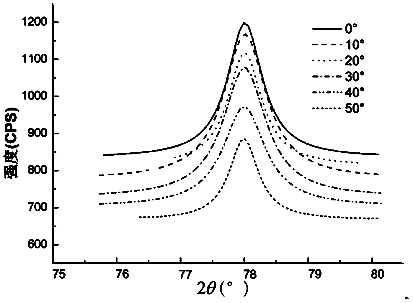
[0018] Step 2. Use the Rigaku Smartlab X-ray diffractometer, set the scan start angle to 2θ-2°, the scan end angle to 2θ+2°, the scan step to 0.02°, the scan speed to 1° / min, and count The time is 4.00s; the azimuth ψ is respectively selected as 0°, 10°, 20°, 30°, 40° and 50°, and the 2θ of the experimental sample corresponding to...


PUM


Abstract

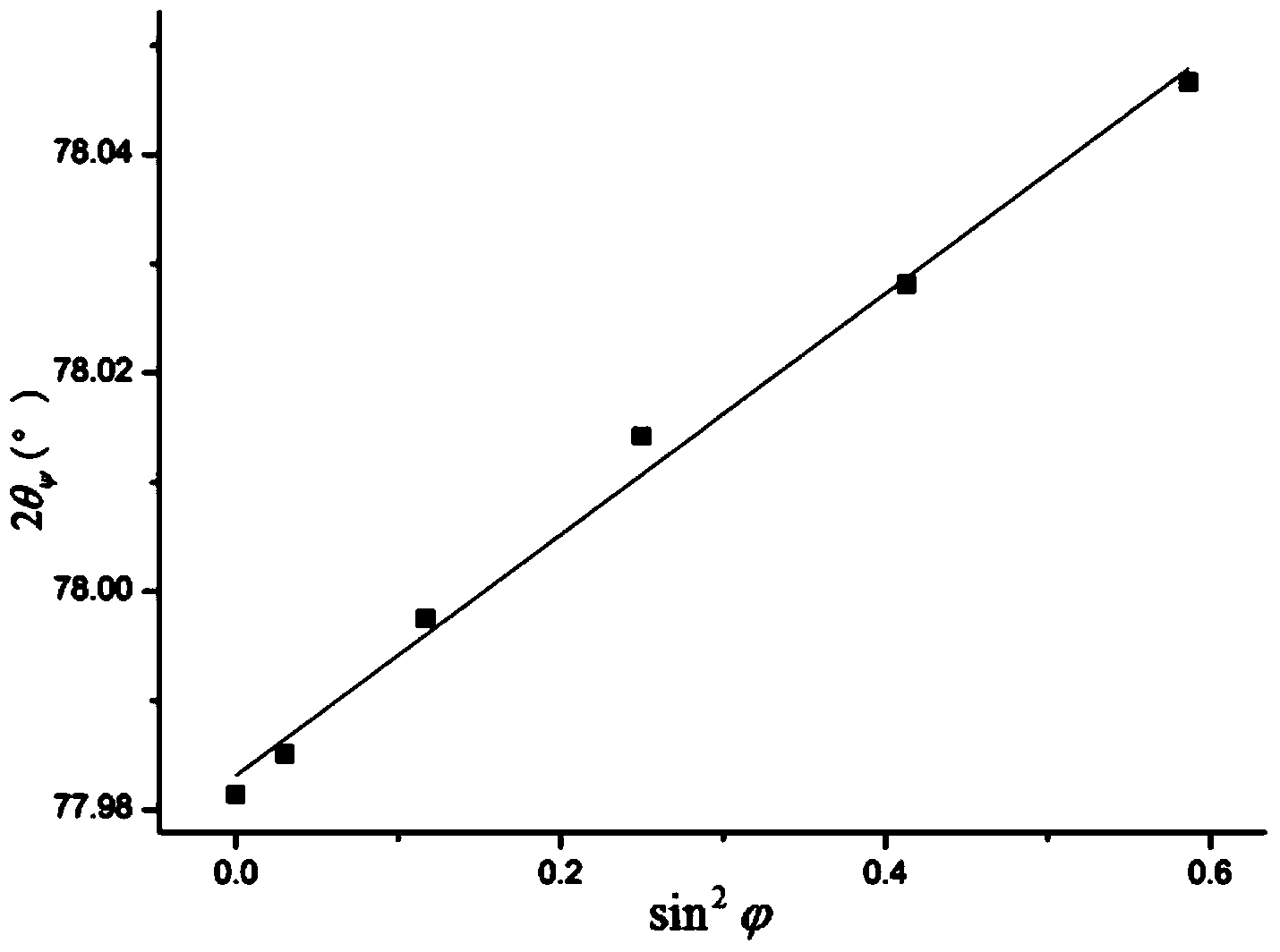
The invention relates to a method for measuring the residual stress of a pyrolytic carbon coating by virtue of X ray diffraction and solves the problem that no complete technique for measuring the residual stress of the pyrolytic carbon coating by virtue of an X ray diffraction method is issued currently. The method comprises the following specific steps: carrying out conventional X-ray detection on an experimental sample to obtain a full diffraction spectrum, and determining a maximal diffraction angle 2theta of a diffraction peak; setting a scanning starting angle, a scanning end angle, a scanning step, a scanning speed and a counting time, selecting six azimuth angles psi, measuring a crystal face diffraction angle 2thetapsi, corresponding to each azimuth angle psi, of the experimental sample, counting sin<2>psi corresponding to each azimuth angle psi, drawing a 2thetapsi-sin<2>psi dispersing graph, and fitting according to each discrete point so as to obtain a straight slope formula (described in specification); calculating a residual stress value formula (described in specification), wherein E represents elasticity modulus of the experimental sample, v represents Poisson's ratio of the experimental sample, and theta0 is a half-crystal face diffraction angle when the experimental sample is not stressed. According to the method, the residual stress value of the pyrolytic carbon coating can be simply, conveniently and accurately obtained on the premise that the coating is not damaged.

Description

technical field [0001] The invention belongs to the technical field of testing and relates to an X-ray diffraction method, in particular to a method for measuring the residual stress of a pyrolytic carbon coating by X-ray diffraction. Background technique [0002] Pyrolytic carbon coatings prepared by fluidized bed chemical vapor deposition (CVD) process will have residual stress during the deposition process. The residual stress is related to the deposition process and deposition conditions, and also affects the structure and performance of the pyrolytic carbon coating. The strength of the coating can be improved by preparing the pyrolytic carbon coating with an appropriate residual stress. For the pyrolytic carbon coating of the artificial heart valve, it is required to have an appropriate compressive stress in the coating, so as to prevent the valve from cracking under the impact of blood. Therefore, it is of far-reaching significance to quantitatively measure the resid...

Claims


Application Information

Patent Timeline
Patent Type & Authority Applications(China)
IPC IPC(8): G01N23/20
Inventor 张建辉喻主路杨欢郑艳真李威龙
Owner HANGZHOU DIANZI UNIV
Learn More