
A detection method for improving the resolution of area array probes

A detection method and resolution technology, which is applied in the field of ultrasonic flaw detection, can solve problems such as increased power consumption, resolution less than 1.25mm, and increased cost of flaw detectors, achieving low cost, improved sampling resolution, and clear and accurate flaw detection results Effect

Active Publication Date: 2016-04-27
NDT TECH SHANGHAI
View PDF11 Cites 0 Cited by
  • Summary
  • Abstract
  • Description
  • Claims
  • Application Information

AI Technical Summary

Problems solved by technology

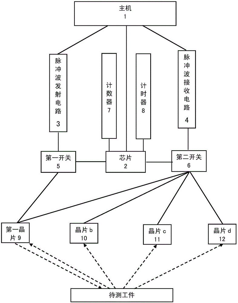
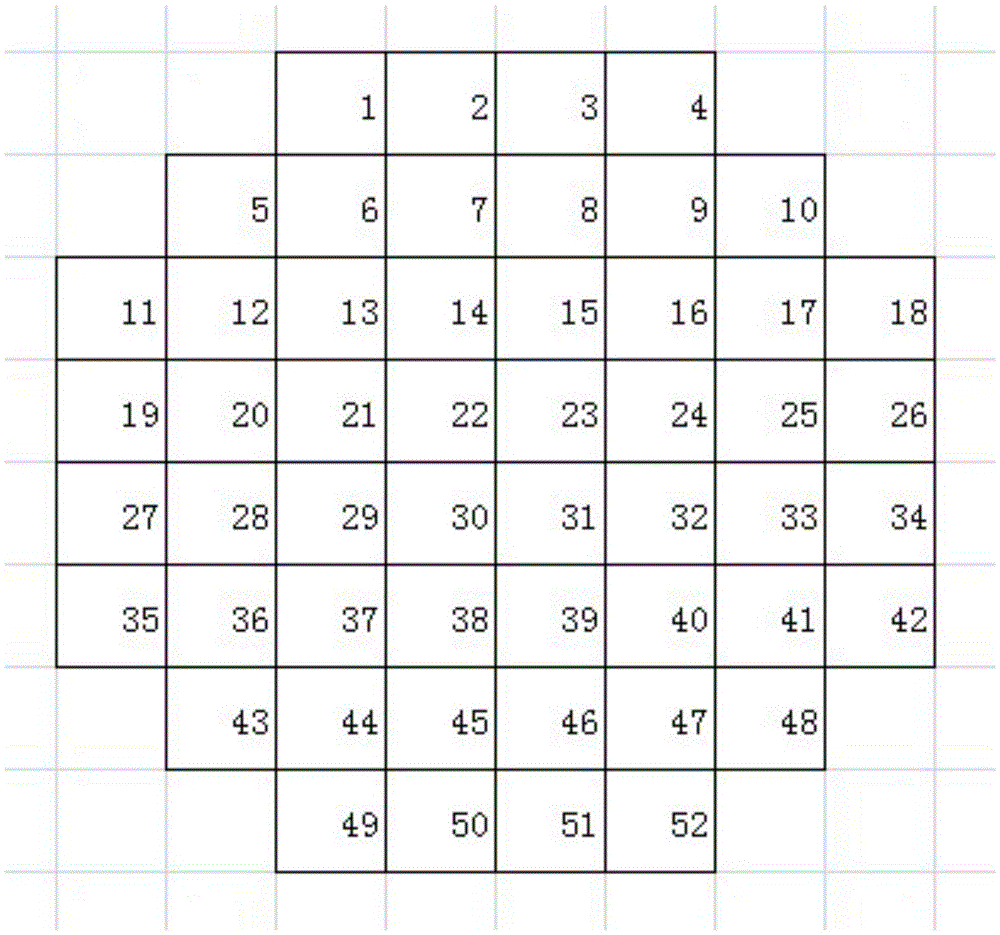
[0003] The wafer is the core part of the ultrasonic flaw detector. The pulse wave is transmitted to the workpiece to be tested through the wafer, and the pulse wave reflected by the workpiece to be tested is processed and analyzed to obtain the defect pattern of the workpiece to be tested. In the prior art, the Take a 10mm diameter probe as an example, 52 chips are required in an 8*8 chip array, and only when the distance between chips reaches 1.25mm can the 10mm diameter range of the probe be covered, and each chip is working independently. Receive the pulse wave, which leads to the fact that the resolution of the flaw detector is less than 1.25mm when the wafer spacing is 1.25mm, and the parts cannot be accurately detected. If the resolution is increased by increasing the number of wafers, then the flaw detector will inevitably be improved. cost, and power consumption will increase

Method used


Image

  • A detection method for improving the resolution of area array probes
  • A detection method for improving the resolution of area array probes

Examples


Embodiment

[0063] like figure 2 As shown, there are 52 chips on the ultrasonic area array probe with a diameter of 10mm, and the 52 chips are arranged in the form of an area array, and the timer 8 connected with the chip 2 presets a fixed time interval, and the chip 2 is controlled by The first switch 5 connected with the pulse wave transmitting circuit connects the pulse wave transmitting circuit 3 with the first chip 9, and the first chip 9 emits the pulse wave for the first time to the workpiece to be tested. Meanwhile, the chip 7 passes the control and The second switch 6 that the pulse wave receiving circuit 4 is connected controls the pulse wave receiving circuit 4 to be connected with the first chip 9, and the first chip 9 receives the pulse wave that the workpiece to be measured reflects back; The chip 2 sends the time signal, and after receiving the time signal, the chip 2 controls the first chip 9 to emit the second pulse wave to the workpiece to be tested. At the same time, t...


PUM


Abstract

The invention provides a detection method for improving the resolution of an area array probe, comprising the following steps: step 1, having N wafers on the ultrasonic area array probe, and the N wafers are arranged in the form of an area array; step 2, The chip controls the chip a to emit m times of pulse waves to the workpiece to be measured; step 3, the pulse waves reflected by the workpiece to be measured are respectively received by chip a and m-1 chips adjacent to chip a; step 4 , when the N wafers all emit m times of pulse waves, and the pulse waves reflected by the workpiece to be tested are all received; Step 5, repeat the process from Step 1 to Step 4 until the flaw detection is completed; Step 6, the host will The received pulse wave is analyzed and processed to obtain the defect pattern of the workpiece to be tested, which is displayed on the monitor on the host. The invention has the advantage of greatly improving the resolution of the area array detector.

Description

technical field [0001] The invention relates to the technical field of ultrasonic flaw detection, in particular to a detection method for improving the resolution of an area array probe. Background technique [0002] In the non-destructive testing of metal test pieces and parts, ultrasonic flaw detection technology is an important means. When ultrasonic waves propagate in the material to be tested, the acoustic properties of the material and changes in the internal organization have a certain impact on the propagation of ultrasonic waves. The technology of detecting material performance and structural changes through the detection of the degree and condition of ultrasonic waves is called ultrasonic testing. . Ultrasonic flaw detection is a method of detecting defective parts by using the characteristics of ultrasonic waves penetrating into the metal and passing from one section to another section, reflecting at the edge of the section. [0003] The wafer is the core part o...

Claims


Application Information

Patent Timeline
Patent Type & Authority Patents(China)
IPC IPC(8): G01N29/04
CPCG01N29/262G01N2291/044G01N2291/106G01N29/04G01N29/44G01N2291/023G01N2291/0289
Inventor 张瑞
Owner NDT TECH SHANGHAI
Learn More