Waveguide display based on diffractive optical element

A technology for diffractive optical elements and waveguide displays, which is applied in the directions of optical elements, light guides, optics, etc., can solve problems such as the limitation of the viewing angle of the waveguide display, and achieve the effect of solving the limited viewing angle.

Active Publication Date: 2014-09-10
BEIJING INSTITUTE OF TECHNOLOGYGY
View PDF5 Cites 31 Cited by
  • Summary
  • Abstract
  • Description
  • Claims
  • Application Information

AI Technical Summary

Problems solved by technology

[0005] The technical problem to be solved by the present invention is how to solve the problem that the viewing angle of existing waveguide displays based on diffractive optical elements is limited

Method used


Image

  • Waveguide display based on diffractive optical element
  • Waveguide display based on diffractive optical element
  • Waveguide display based on diffractive optical element

Examples


Embodiment Construction

[0023] Embodiments of the present invention will be further described in detail below in conjunction with the accompanying drawings and examples. The following examples are used to illustrate the present invention, but should not be used to limit the scope of the present invention.

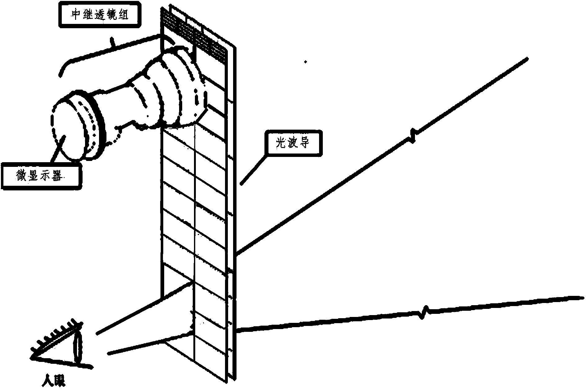
[0024] The display system of the see-through waveguide display in the prior art is as figure 1 As shown, the relay optical system is included, so that the overall volume and weight of the display system are significantly increased, and the viewing angle of the display is obviously limited.

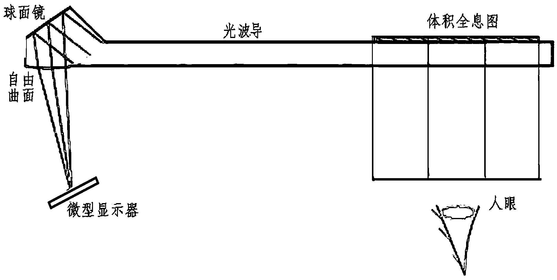
[0025] This embodiment provides a waveguide display based on a diffractive optical element, including an image source, an input coupler, an output coupler, and a flat optical waveguide, and the output coupler is a multiplexing volume holographic grating. Wherein the multiplexing volume holographic grating is three volume holograms recorded on the same medium material. The volume hologram is a reflective holo...


PUM


Abstract

The invention discloses a waveguide display based on a diffractive optical element. The waveguide display comprises an image source, an input coupler, an output coupler and a planar optical waveguide, wherein the output coupler is a multiplexed volume holographic grating. By adopting the structure, the problem of limitation on the field angle of the conventional waveguide display based on the diffractive optical element is solved. The waveguide display can be widely applied to the field of waveguide displays.

Description

technical field [0001] The invention relates to a waveguide display, in particular to a waveguide display based on diffractive optical elements. Background technique [0002] Existing see-through optical waveguide displays are mainly composed of an image source, a relay optical system, an input coupler, an output coupler (beam combiner), and a flat optical waveguide. According to the output coupler (beam combiner, combiner, there are usually two channels, so that the transmitted beam enters the human eye, and at the same time, the virtual image of the image source after coupling through the waveguide enters the human eye, so that the human eye can observe a picture superimposed on the real image. Virtual image above the scene) category, including waveguide displays based on coated mirror arrays and waveguide displays based on diffractive optical elements. The disadvantage of waveguide displays based on coated mirror arrays is severe ghosting, whether for a single wavelength...

Claims


Application Information

Patent Timeline
Patent Type & Authority Applications(China)
IPC IPC(8): G02B6/122G02B6/124G02B6/00G03H1/04
Inventor 刘娟韩剑王涌天
Owner BEIJING INSTITUTE OF TECHNOLOGYGY
Why Eureka
Try Eureka