
A monitoring device for distance detection and picture transmission at the front end of a crane jib

A monitoring device and distance detection technology, which is applied in safety devices, transportation and packaging, and load hanging components, etc., can solve problems such as command errors by commanders, limited vision of crane operators, improper operation of crane operators, etc., and achieve improvement Work efficiency, solve the problem of limited field of view, and quick installation

Pending Publication Date: 2022-02-25
SHANGHAI CHUANGPING INFORMATION TECH
View PDF0 Cites 0 Cited by
  • Summary
  • Abstract
  • Description
  • Claims
  • Application Information

AI Technical Summary

Problems solved by technology

Therefore, during the actual operation of the crane, improper operation of the crane operator or incorrect command by the commander often occurs, resulting in the collision of the crane arm and damaging the line, which poses a greater threat to the safety of the crane operator and property.
At present, there is no good equipment to solve the problem of limited field of vision for the actual operator of the crane

Method used


Image

  • A monitoring device for distance detection and picture transmission at the front end of a crane jib
  • A monitoring device for distance detection and picture transmission at the front end of a crane jib
  • A monitoring device for distance detection and picture transmission at the front end of a crane jib

Examples


Embodiment Construction

[0020] The embodiment of the present invention provides a monitoring device for distance detection and picture transmission at the front end of the crane arm, which is suitable for observing the distance detection of obstacles in front of the crane arm and taking pictures during the operation of the crane

[0021] The present invention will be further elaborated below in combination with specific embodiments and accompanying drawings. It should be understood that the described embodiments are only used to illustrate the present invention and not to limit the scope of the present invention. In addition, it should also be understood that after reading the content taught by the present invention, all other embodiments obtained by those of ordinary skill in the art based on the embodiments of the present invention without making creative efforts, these equivalent forms also fall into the within the scope defined by the appended claims of this application.

[0022] It should be no...


PUM


Abstract

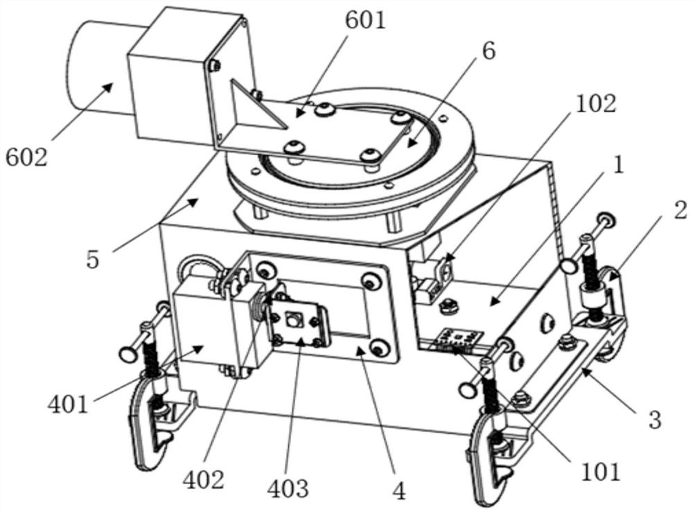
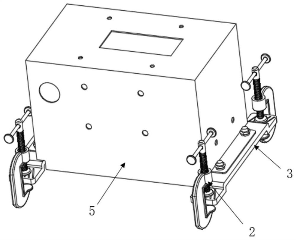
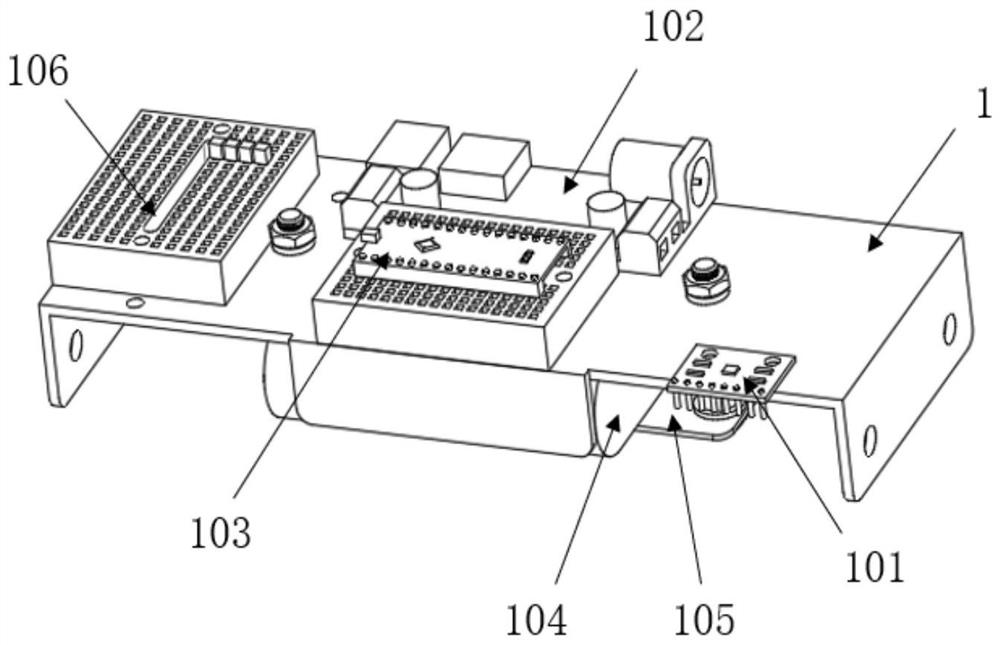
The invention particularly relates to a monitoring device for distance detection and picture transmission at the front end of a crane jib. Comprising a laser radar, a single-degree-of-freedom rotating holder, a laser radar rotating steering engine, a camera steering engine fixing L-shaped support, a camera balancing L-shaped support, a camera rotating steering engine, a box body fixing clamping plate, a G-shaped clamp, a circuit fixing bottom plate, a camera balancing control plate, a power supply voltage stabilizing control plate and a gyroscope. A circuit fixing bottom plate is arranged in the device box body; a camera balance control panel, a gyroscope and a power supply voltage stabilization control panel are fixed on the upper side of the bottom plate; a camera balancing support is mounted in front of the device box body; the balance support fixes the control steering engine and the camera. The view angle of the camera is kept horizontal through an internal camera balance control panel and a gyroscope according to the rotation degree of the box body; a single-degree-of-freedom rotating holder is arranged above the device box body; an offset laser radar is fixed on the holder, and the laser radar realizes distance measurement of a front obstacle through an external program. The whole device is fixed to a front side protection plate of a crane jib through the clamping plate. The laser radar is arranged at the front end of the crane jib to detect the front physical distance, the camera is installed to achieve image transmission of the front end of the crane jib, crane operators can be effectively helped to know the situation of the front end of the crane jib in real time, the crane jib is prevented from colliding with objects in front, and the personal safety of the operators is guaranteed.

Description

technical field [0001] The invention relates to a monitoring device for distance detection and picture transmission at the front end of a crane arm Background technique [0002] Cranes are important equipment for assisting high-altitude operations. Generally, the boom of a crane can be extended by more than 10 meters. For large cranes, the boom can reach tens or even hundreds of meters. At present, during the process of cable replacement, transformer replacement and line maintenance by the employees of the power supply bureau, and during the operation of the crane by the designer, due to the long distance between the crane operating cab and the front end of the boom, the operator cannot directly observe the obstacles at the front end of the boom The situation is mainly carried out by auxiliary personnel on-site command. The actual operation process has higher requirements on the command and observation ability of the auxiliary personnel. Therefore, during the actual operat...

Claims


Application Information

Patent Timeline
IPC IPC(8): B66C13/46B66C13/16B66C15/00
CPCB66C13/46B66C13/16B66C15/00
Inventor 罗剑
Owner SHANGHAI CHUANGPING INFORMATION TECH
Learn More