Battery module and method for connecting battery modules in series

A battery module and battery technology, applied in battery circuit devices, current collectors, electric vehicles, etc., can solve the problems of reduced battery module life, reduced battery module life, inconsistent aging speed of battery module 1 and battery module 2, etc., to avoid The effect of inconsistent discharge current and consistent aging speed

Active Publication Date: 2016-05-11
VERTIV CORP
View PDF3 Cites 0 Cited by
  • Summary
  • Abstract
  • Description
  • Claims
  • Application Information

AI Technical Summary

Problems solved by technology

[0011] It can be seen from the above table (1) that when two battery modules are connected in series, since the load of battery module 1 takes power differently from the load of battery module 2, it is very likely that the battery pack of battery module 1 and The discharge current of the battery pack of battery module 2 is not completely consistent, which leads to inconsistent aging speeds of battery module 1 and battery module 2. After long-term operation, the two battery modules are equivalent to full and weak batteries or new and old batteries used in series. The life of each battery module is greatly reduced. Similarly, when more than 2 battery modules are used in series, the load power of each battery module is not exactly the same, which will also lead to a reduction in the life of each battery module.

Method used


Image

  • Battery module and method for connecting battery modules in series
  • Battery module and method for connecting battery modules in series
  • Battery module and method for connecting battery modules in series

Examples


Embodiment 1

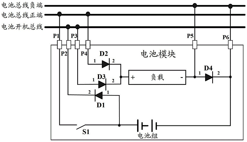
[0045] Such as image 3 As shown, it is a schematic structural diagram of the battery module in Embodiment 1 of the present invention. The battery module is connected to the external battery bus positive terminal, the battery bus negative terminal and the battery power-on bus to provide power for the external module and its own load, including : the first diode D1, the second diode D2, the third diode D3, the fourth diode D4, the first switch S1, the load and the battery pack, and, for connecting to the positive terminal of the battery bus The first interface P1 and the fourth interface P4, the second interface P2 and the third interface P3 for connecting to the battery power-on bus, the fifth interface P5 and the sixth interface P6 for connecting to the negative end of the battery bus, wherein:

[0046] The first switch S1 is used to control the battery module to access and withdraw from the positive terminal of the battery bus;

[0047] The first diode D1 is used to enable ...

Embodiment 2

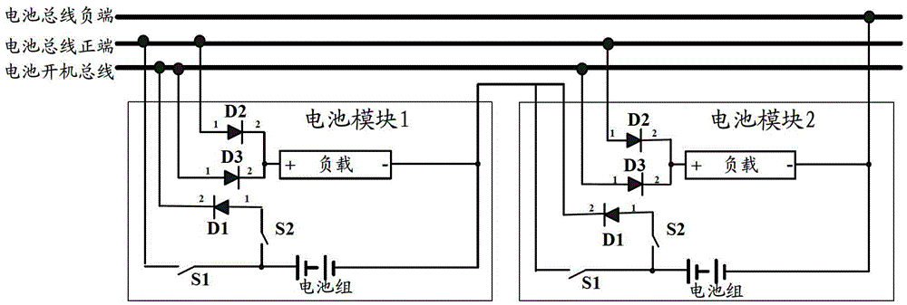
[0073] Such as Figure 6 As shown, it is a schematic structural diagram of the power supply device provided by Embodiment 2 of the present invention, Figure 6 The power supply device in the battery is composed of two battery modules (the first battery module and the second battery module). The load of the included battery module provides power supply, and the first battery module and the second battery module are as in the first embodiment image 3 the battery module shown;

[0074] exist Figure 6 middle, D 11 、D 12 、D 13 and D 14 respectively represent the first to fourth diodes of the first battery module;

[0075] P 11 ,P 12 ,P 13 ,P 14 ,P 15 and P 16 respectively represent the first to sixth interfaces of the first battery module;

[0076] S 11 representing the first switch of the first battery module;

[0077] L 1 Represents the load of the first battery module;

[0078] B 1 a battery pack representing the first battery module;

[0079] D. 21 、D 22...

Embodiment 3

[0109] In the case of N battery modules connected in series, due to the diode D of the Nth battery module N4 is connected to the negative terminal of the battery bus and the load L of the Nth battery module N The wire at the negative end of the short circuit has no effect on the entire circuit, but at this time, even if the Nth battery module does not have a diode D N4 , the Nth battery module still draws power from the voltage of the battery packs of N battery modules connected in series. Therefore, in Embodiment 3 of the present invention, another power supply device is provided:

[0110] The power supply device is connected to the external battery bus positive terminal, battery bus negative terminal and battery power-on bus to provide power for external modules and their own loads, including an existing battery module and N-1 battery modules as described in Embodiment 1 The existing battery module includes all the devices in the battery module described in Embodiment 1 exc...


PUM


Abstract

The invention discloses a battery module and a method for connecting battery modules in series. The main content is as follows: the battery module is connected with the positive end of a battery bus, the negative end of the battery bus and a battery power-on bus to power external modules and be self-powered; the battery module comprises first to fourth diodes, a first switch, a load, a battery pack, and first to sixth interfaces; and the negative electrode of the battery pack is connected with the negative end of the battery bus through the sixth interface and is connected with the negative end of the load through the fourth diode, and the negative end of the load is connected with the negative end of the battery bus through the fifth interface. As the fourth diode with reverse cut-off characteristic is added between the negative end of the load and the negative electrode of the battery pack, and a wire is added between the negative end of the load and the negative end of a power bus, a plurality of battery modules only take electricity from the battery bus when being connected in series, the discharge currents of the battery modules are consistent, and service life shortening of the battery module is avoided.

Description

technical field [0001] The present invention relates to the technical field of uninterruptible power supply (Uninterruptible Power Supply, UPS), in particular to a battery module and a method for connecting battery modules in series. Background technique [0002] At present, in the design of modular UPS, it is often equipped with an intelligent battery module. The power supply is provided by itself and the external module. The internal structure diagram of the battery module is as follows: figure 1 shown. [0003] exist figure 1 Among them, 1 on the left or right side of each diode represents the anode of the diode, 2 represents the cathode of the diode, the positive pole of the battery pack is connected to the positive terminal of the battery bus via the first switch S1, and the negative pole of the battery pack is respectively connected to the negative terminal of the battery bus and the load (including control chip, drive circuit and detection circuit, etc.), while the...

Claims


Application Information

Patent Timeline
Patent Type & Authority Patents(China)
IPC IPC(8): H02J7/00
Inventor 卢军
Owner VERTIV CORP
Why Eureka
Try Eureka