Bus bar capacitor discharge method, system and device for power device

A technology of power devices and bus capacitors, applied in the direction of output power conversion devices, control systems, motors, etc., can solve problems such as hazards

Active Publication Date: 2019-01-18
NIO ANHUI HLDG CO LTD
View PDF5 Cites 4 Cited by
  • Summary
  • Abstract
  • Description
  • Claims
  • Application Information

AI Technical Summary

Problems solved by technology

The active discharge method using the motor winding mainly uses the equivalent resistance of the motor winding to consume the electric energy in the bus capacitor. When the discharge is out of control, the motor may generate unexpected motor torque, which is potentially harmful.

Method used


Image

  • Bus bar capacitor discharge method, system and device for power device
  • Bus bar capacitor discharge method, system and device for power device
  • Bus bar capacitor discharge method, system and device for power device

Examples


Embodiment approach 1

[0205] In this embodiment, the power device includes a first active short-circuit control module. Specifically, see the attached Figure 4 , Figure 4 The control mode of the half-bridge circuit in this embodiment is shown as an example. In this embodiment, the DC bus capacitor can be discharged according to the following steps:

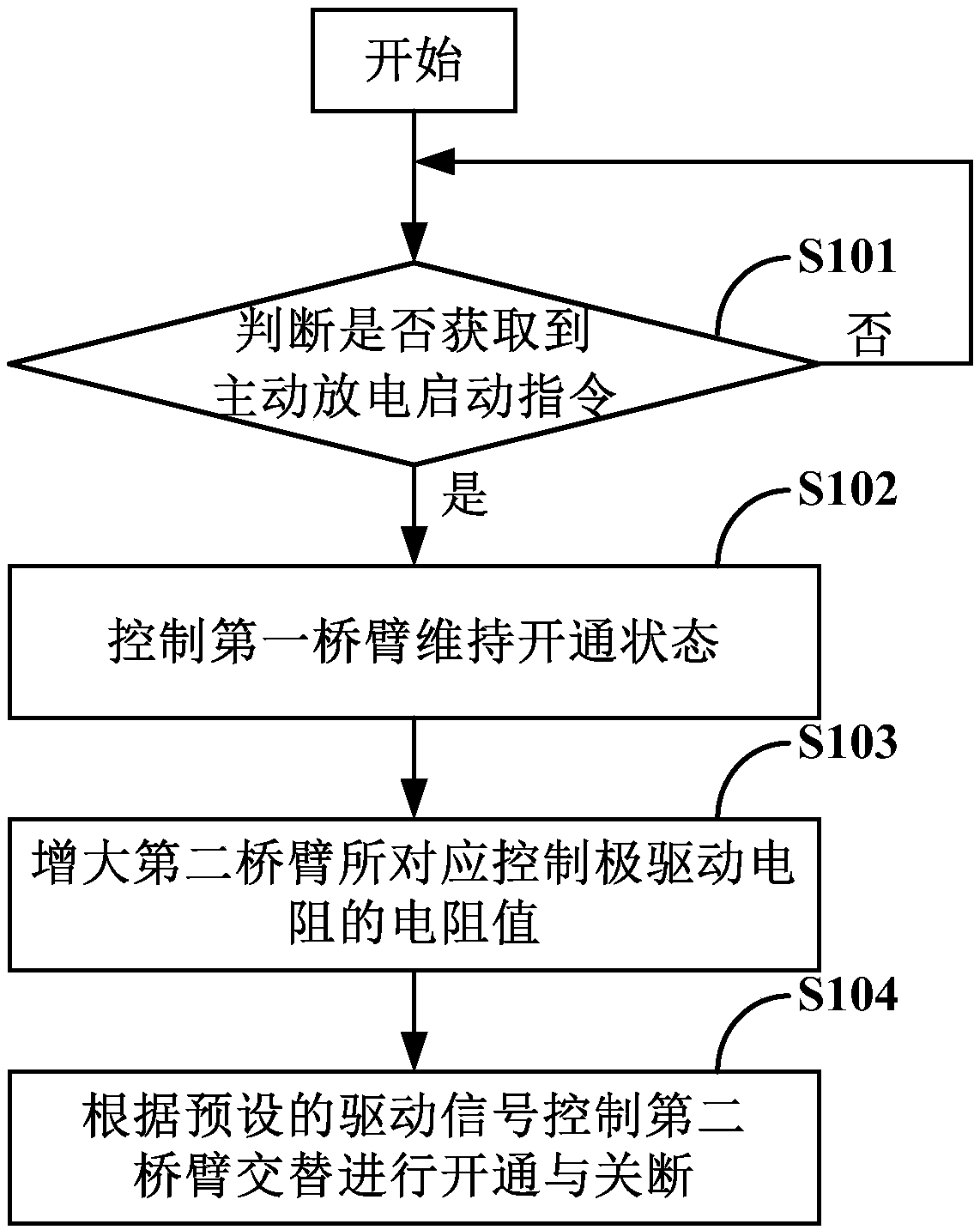
[0206] Step 1: Determine whether the active discharge start command is obtained: if yes, go to step 2; if not, continue to obtain the active discharge start command.

[0207] Step 2: Use the driver module of the lower bridge arm ( Figure 4 The driving module connected to IGBT2) controls the power semiconductor device IGBT2 in the lower bridge arm to turn on.

[0208] When the active circuit protection of the motor is required during the discharge process, according to the short circuit control signal ( Figure 4 The shown pulse signal ASC_CMD) triggers to start the first active short-circuit control module corresponding to IGBT2, and the first ...

Embodiment approach 2

[0213] In this embodiment, the power device includes a second active short-circuit control module. Specifically, see the attached Figure 5 , Figure 5 The control mode of the half-bridge circuit in this embodiment is shown as an example. In this embodiment, the DC bus capacitor can be discharged according to the following steps:

[0214] Step 1: Determine whether the active discharge start command is obtained: if yes, go to step 2; if not, continue to obtain the active discharge start command.

[0215] Step 2: Control the second active short-circuit control module ( Figure 5 The second active short-circuit control module connected to the shown IGBT2) according to the short-circuit control signal ( Figure 5 The shown pulse signal ASC_CMD) controls the power semiconductor device IGBT2 in the lower bridge arm to turn on.

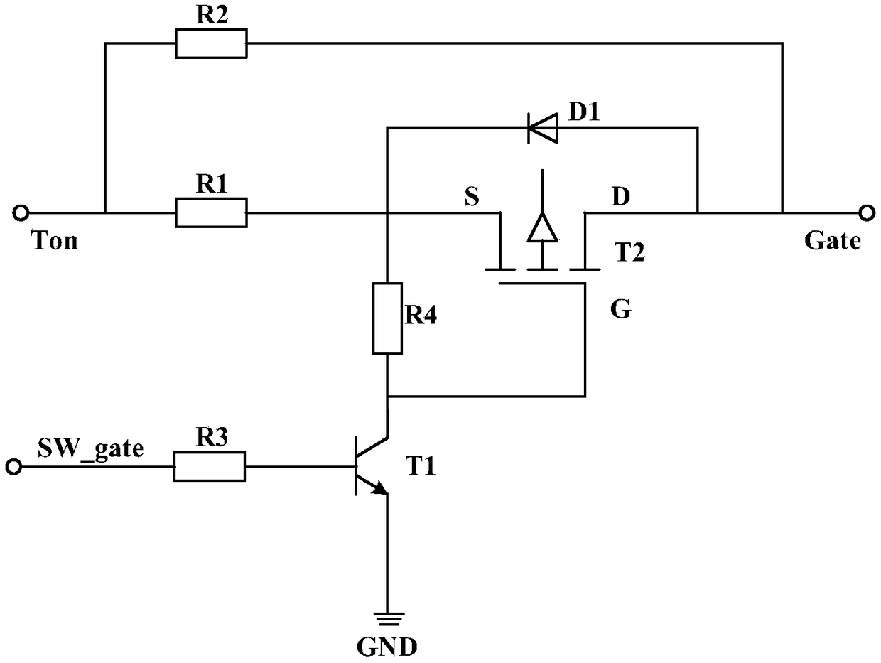
[0216] Step 3: Switch the gate drive resistor of the power semiconductor device IGBT1 in the upper bridge arm to a resistor Rgon_large with a larger re...


PUM


Abstract

The invention relates to the technical field of power electronics, in particular to a bus bar capacitor discharge method, system and device for power device, aiming at solving the technical problem ofhow to discharge the busbar capacitance actively effectively and reliably. For this purpose, the method provided by the invention mainly comprises the following steps: controlling the first axle armto maintain the on state, increasing the resistance value of the driving resistance of the corresponding control pole of the second axle arm, and controlling the second axle arm to alternately turn onand off according to the driving signal. Based on the above steps, no additional circuit structure is required in the power device, and the electric energy of the DC bus capacitor can be gradually released by controlling the half-bridge circuit to pass through for a plurality of short times (the half-bridge circuit and the DC bus capacitor form a conductive loop in the straight-through state). Atthat same time, the through time of the half-bridge circuit can be control by adjusting the resistance value of the drive resistor of the control pole and the duty ratio of the positive conduction voltage of the power semiconductor device, and the problem of out-of-control discharge can be effectively solved.

Description

technical field [0001] The present invention relates to the technical field of power electronics, in particular to a bus capacitor discharge method, system and device for power devices. Background technique [0002] The electric drive system (Electric Drive System, EDS) of a new energy vehicle usually has a high-capacity bus capacitor (such as a bus capacitor with a value of hundreds of microfarads or more). When the main relay of the power battery is disconnected, there will be more residual charge on the bus capacitor and its capacitor voltage will be equal to the output voltage of the power battery. The output voltage of the power battery is often as high as hundreds of volts (such as between 250V and 450V). In order to avoid the high voltage on the bus capacitor from causing harm to the human body, it is necessary to discharge the bus capacitor immediately after the main relay is disconnected. [0003] The discharge method of bus capacitor mainly includes passive discha...

Claims


Application Information

Patent Timeline
Patent Type & Authority Applications(China)
IPC IPC(8): H02M1/32H02P27/06B60L15/00
CPCB60L15/007H02M1/32H02P27/06H02M1/322Y02T10/64
Inventor 苏谢祖张帆张煜洪文成单亮路红亮杜永红陈伟谢启河
Owner NIO ANHUI HLDG CO LTD
Why Eureka
Try Eureka