
Solar cell module

a solar cell and module technology, applied in the field of solar cell modules, can solve the problems of thermal damage resin and flux residue, and achieve the effect of reducing the output of solar cell modules and increasing the resistance valu

Active Publication Date: 2010-02-11
SANYO ELECTRIC CO LTD
View PDF7 Cites 15 Cited by
  • Summary
  • Abstract
  • Description
  • Claims
  • Application Information

AI Technical Summary

Benefits of technology

The present invention provides a solar cell module that can restrain a decrease in output. The invention achieves this by reducing the accumulation of damage and flux residue in the alloy layer formed by soldering the electrodes and wiring member. This is achieved by using an adhesive layer made of a resin with a smaller residual stress than the bus bar electrode. The adhesive layer can be any one of epoxy resin, imide resin, and phenol resin with an elastomer mixed therein or made of an epoxy resin, imide resin, or phenol resin with an elastomer. The invention also addresses the issue of reduced output caused by stress concentration on the alloy layer by introducing a soft molecular skeleton or higher molecular weight into the resin of the adhesive layer.

Problems solved by technology

In the conventional solar cell module, however, a thermally-damaged resin, a flux residue, and the like accumulate in the alloy layer formed by soldering the electrode and the wiring member.

Method used


Image

  • Solar cell module
  • Solar cell module

Examples


examples

[0053]Hereinafter, the solar cell module according to the present invention is specifically described with reference to Example. However, the present invention is not limited to Example illustrated below, and thus can be carried out appropriately while being modified without departing from the gist thereof.

example

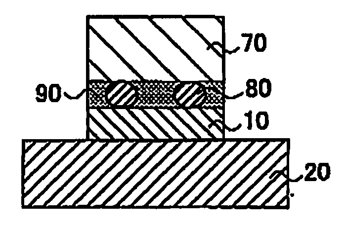
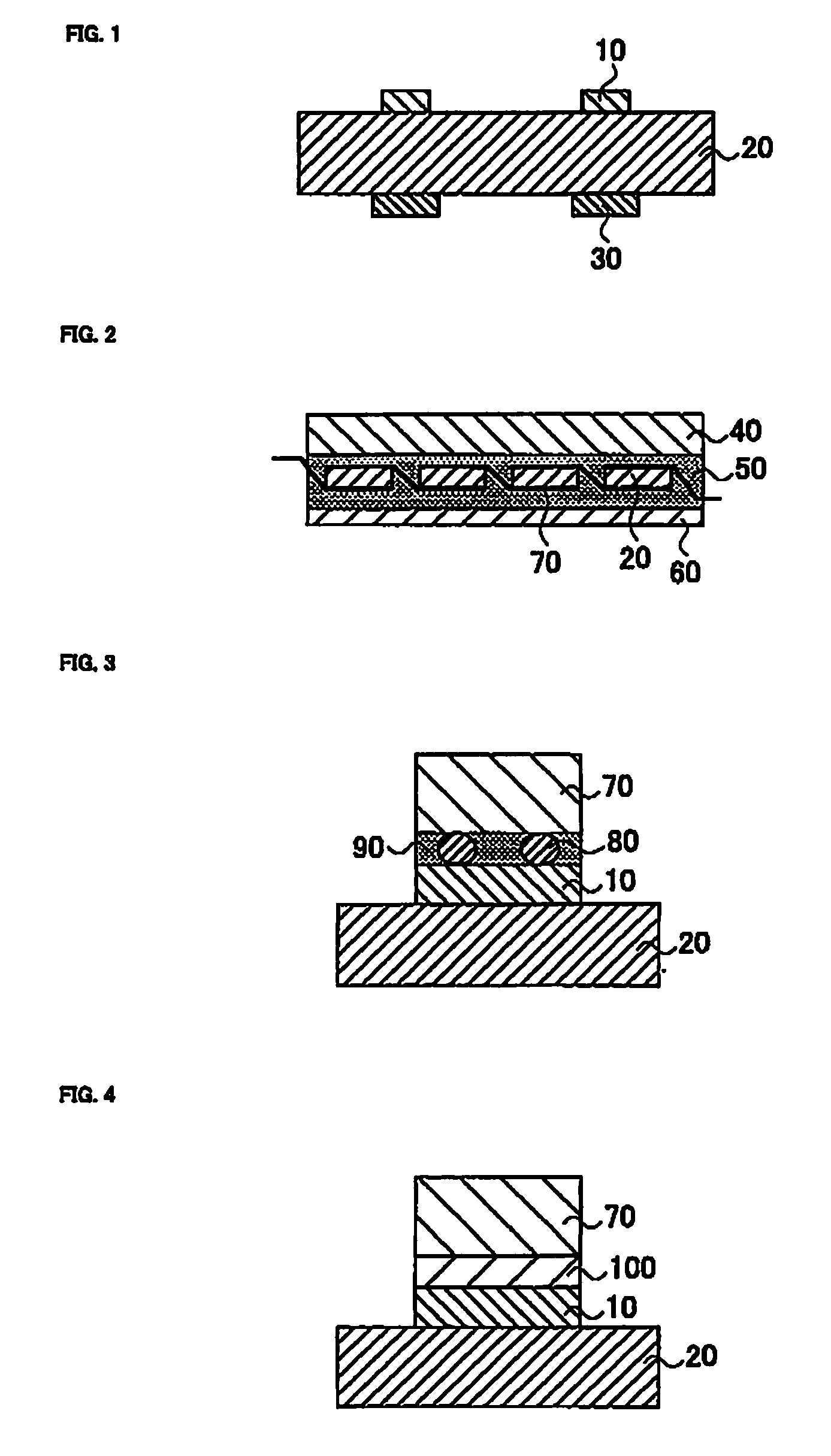
[0054]As a solar cell module according to Example of the present invention, one with the solar cells as shown in FIG. 3 was manufactured as follows. The solar cells according to Example are HIT solar cells.

[0055]Firstly, a resin made of an epoxy resin was mixed with silver particles at a ratio of 20:80 to 10:90 wt %, the silver particles being a mixture of approximately l-μmφ spherical powders and approximately 10-μmφ flake powders. Thereby, a paste was prepared. The viscosity of the paste was adjusted with an organic solvent in an amount of approximately 0.5 to 5% relative to the entire content. This paste was patterned on each of the solar cells by a screen-printing method. The paste was then hardened in conditions of 200° C. for 1 hour, and thereby a collecting electrode including a bus bar electrode was formed.

[0056]Subsequently, a resin made of an epoxy resin to serve as an adhesive layer was mixed with approximately 10-μmφ spherical tin particles at a ratio of 80:20 to 95:5 wt...


PUM


Abstract

Provided is a solar cell module capable of restraining a decrease in the module output. In the solar cell module, a plurality of solar cells are arranged between a light-receiving surface protection member 40 and a back-surface protection member 60, and electrodes 10, 30 of the solar cells are electrically connected to each other through wiring members 70. Each of the electrodes 10, 30 includes a bus bar electrode formed of a resin-type conductive paste. The solar cell module includes an adhesive layer made of a resin 90 between the bus bar electrode and the wiring member 70. Moreover, the residual stress of the resin 90 of the adhesive layer is smaller than the residual stress of a resin contained in the bus bar electrode.

Description

TECHNICAL FIELD[0001]The present invention relates to a solar cell module in which a plurality of solar cells, electrically connected to each other through wiring members, are arranged between a light-receiving surface protection member and a back-surface protection member.BACKGROUND ART[0002]Conventionally, in a solar cell module, wiring members are soldered onto electrodes respectively of a plurality of solar cells to electrically connect the solar cells to each other. In many cases, each of the electrodes is formed of a conductive paste, and copper foil coated with solder is used as the wiring member. When the electrode is soldered to the wiring member, the conductive paste and the solder form an alloy layer to electrically connect the electrode and the wiring member to each other. Additionally, flux is applied to the surface of the conductive paste and to the surface of the wiring member at the solar cell side to facilitate the soldering (see, for example, Patent Document 1).Pat...

Claims


Application Information

Patent Timeline
Patent Type & Authority Applications(United States)
IPC IPC(8): H01L31/042
CPCH01L31/048H01L31/0512H01L31/022425Y02E10/50
Inventor YOSHIMINE, YUKIHIRO
Owner SANYO ELECTRIC CO LTD
Learn More