Heating element for a hot air device

a technology of heating element and hot air device, which is applied in the direction of air heaters, electric heating, fluid heaters, etc., can solve the problems of reducing airflow, destroying the heating element, and high cost per unit, so as to prevent a large change of resistance value, prevent crack formation, and maintain the effect of adhesion

Inactive Publication Date: 2011-12-22
LEISTER TECHNOLOGIES
View PDF10 Cites 16 Cited by
  • Summary
  • Abstract
  • Description
  • Claims
  • Application Information

AI Technical Summary

Benefits of technology

[0008]The carrier element of the heating resistor has an electrically insulating ceramic material, and the heating conductor has an electrically conductive ceramic material, with the ceramic materials of the carrier element and of the heating conductor being in full surface-to-surface contact with each other. The heating resistor of the heating element according to the invention is based 100 percent on ceramics. The new structural concept simplifies the entire production process, and in particular shortens the manufacturing chain which results in a reduction of the unit costs. The invention makes a novel heating element possible that employs the latest ceramics technology, and whose production process produces a ‘single-piece’ heating resistor where the material of the heating conductor is arranged in full surface-to-surface contact, i.e. with a good thermal transfer, on the carrier element. Due to the resulting effective and, in particular, fast and uniform thermal transfer of the generated heat from the heating conductor to the carrier element it is possible to transfer the heat via a large surface from the heating resistor to the airflow. On the one hand, this diminishes the danger of the heating conductor burning through and, on the other hand, has a favorable effect on the necessary airflow, which minimizes the mechanical stresses on the blower drive system.
[0010]This can be accomplished either by reducing the electrical conductivity of the ceramic material itself or by means of selecting an appropriate geometry factor for the heating conductor. The conductivity of the ceramic can be influenced by a variation of their portions of conductive and non-conductive materials. In addition, an increase of the resistance value for the flow of electricity can be achieved by a built-in effective reduction of the cross-section of the heating conductor.
[0011]In conventional fashion, the heating resistor may have several adjoining disk-shaped carrier elements for the heating conductor, or several oblong carrier elements arranged one inside the other. The carrier elements have built-in air channels for the airflow, or they form such channels in between them, depending on their arrangement. Depending on the number of carrier elements, it may be necessary to use a more or less costly mechanical attachment technique and / or electrical connection technique, which can be especially simple if only one carrier element is used. Advantageously, the carrier element of the heating resistor is a tube made of an insulating ceramic material onto which the heating conductor is applied as a conductive ceramic layer on an inside and / or outside surface. The tube acts as carrier for the heating conductor, and the interior space of the tube acts at the same time as an air channel through which the airflow passes. The conductive ceramic layer of the heating conductor is applied to the tube over a large surface and with a low cross-sectional area. Due to its large surface and its full surface-to-surface connection with the tube, it makes a good heat transfer to the carrier element and the airflow passing by possible. By varying the layer thickness of the conductive ceramic layer, the electrical resistance value of the heating conductor for the heating resistor can be adjusted in a simple manner during the production.
[0012]In a preferred implementation of the invention, an inner and an outer conductive ceramic layer of the tube embrace a face of the carrier element at an air outlet side of the heating resistor of the hot air device, with the ceramic layers butting against each other, thereby establishing an electrical connection. This makes it possible to eliminate special contacting devices on the air outlet side on the face of the heating resistor which would produce an electrically conductive connection of the inner and the outer conductive ceramic layer. The production of the inner and the outer heating conductor as a single piece reduces the assembly costs, which has a positive effect on the cost per unit.
[0020]According to an advanced implementation of the invention, the thermal expansion of the carrier element and of the ceramic layers of the heating conductor of the heating resistor is approximately identical when heated. For this purpose, the ceramic materials for the carrier element and the heating conductor are selected to have an approximately identical expansion coefficient which ensures a durable adhesion within the entire operating temperature range. In addition, this counteracts the formation of cracks of the heating conductor and thereby largely prevents a change of the resistance value. When the hot air device is used correctly, this largely precludes the destruction of the heating element.
[0021]Due to its tubular structure, the heating element according to the invention is especially suitable for installation in a hot air device that is equipped with an external or internal device for generating an airflow. The housing with an air outlet opening has a cylindrical section for holding the heating element, an adjoining section with a blower, for example, and adjoining this a handle section in which a control unit for the heating element and / or the motor are arranged together with a motor for driving the blower. The hot air device may also be operated with an outside air supply; in that case, it contains an additional module with electronics, without a motor or blower. A hot air device equipped in this way is distinguished by an especially functionally reliable and heating element with a long working life.

Problems solved by technology

Such heating elements are costly to manufacture, resulting in high costs per unit.
Also, improper handling, for example, may cause a reduction of the airflow by restricting the air inlet or the air outlet which, in turn, usually leads to the destruction of the heating element due to the heating wire burning through.

Method used


Image

  • Heating element for a hot air device
  • Heating element for a hot air device
  • Heating element for a hot air device

Examples


Embodiment Construction

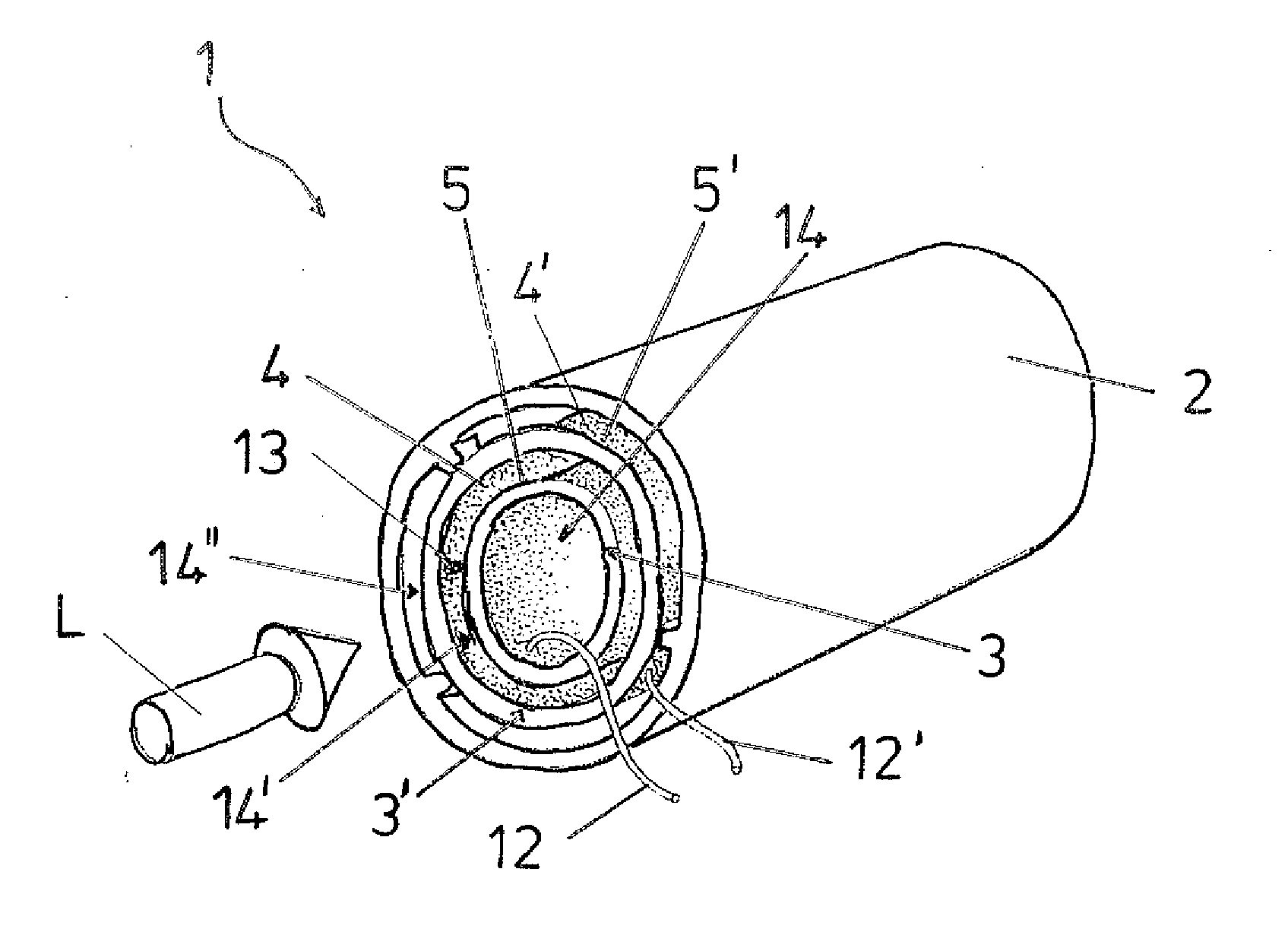
[0029]FIG. 1 shows an implementation of the heating element 1 according to the invention with heating resistors 3, 3′ in a view towards the air inlet side 10 for an airflow L. The two heating resistors 3, 3′ that are essentially tube-shaped are arranged, one nested inside the other, in a holding tube 2, and have carrier elements 5, 5′ that are arranged coaxially one inside the other and have heating conductors 4, 4′.

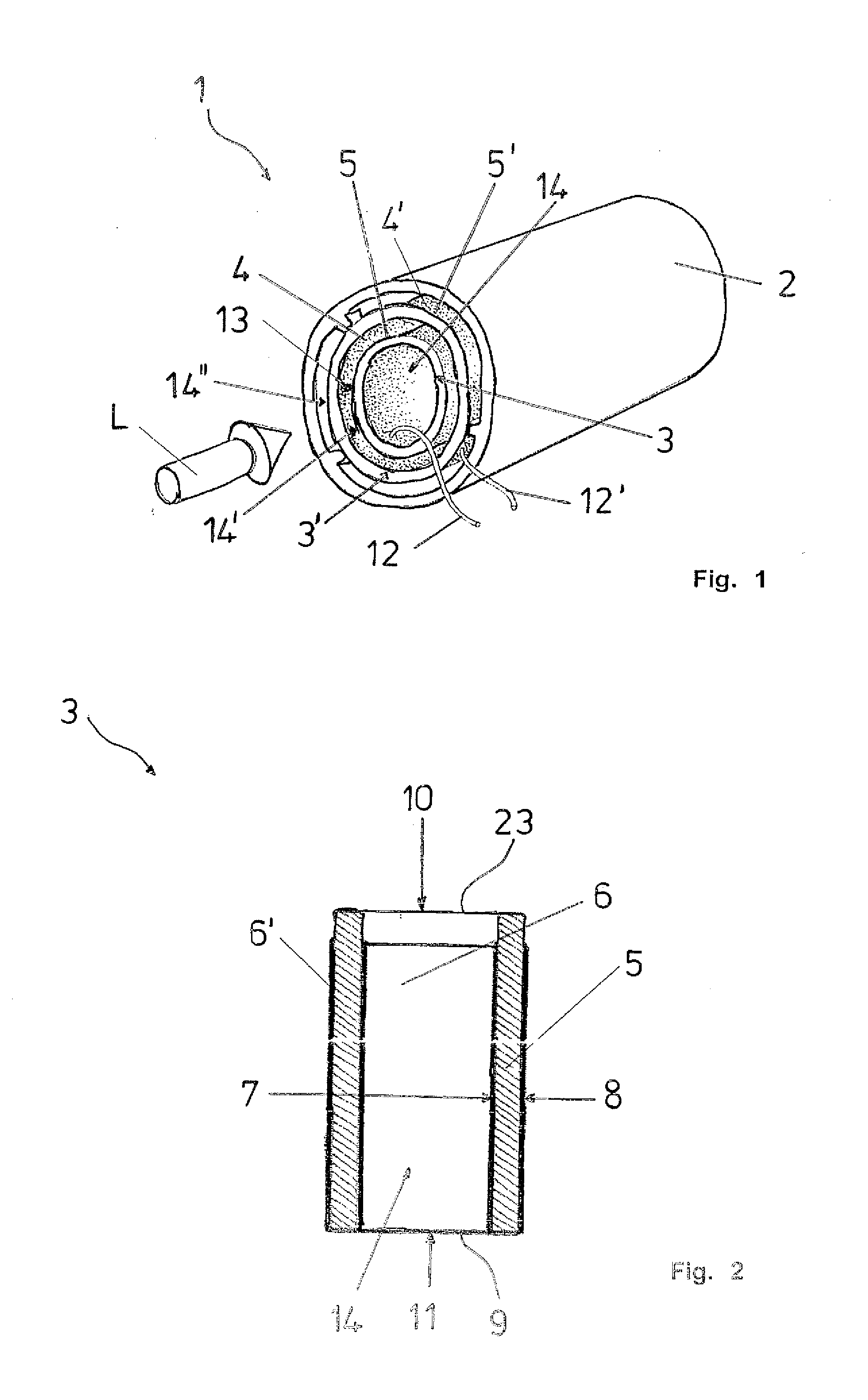
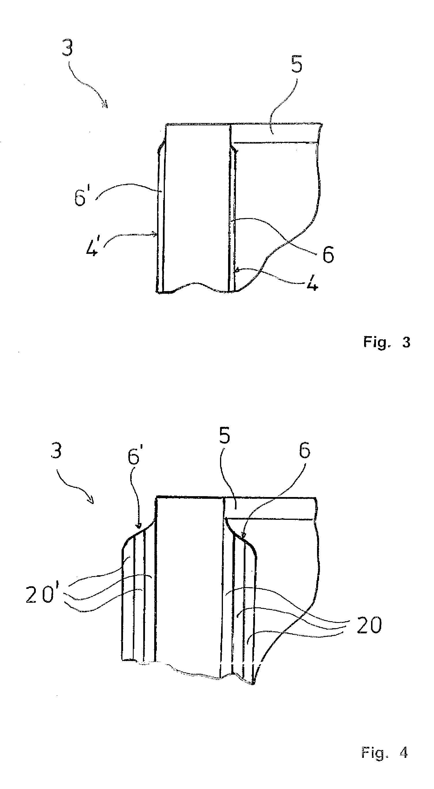
[0030]Like the holding tube 2 and the carrier elements 5, 5′, the heating conductors 4, 4′ are made completely of ceramic material; the holding tube 2 and the carrier elements 5, 5′ are made of an insulating ceramic material and the resistance layers 6, 6′ of the heating conductors 4, 4′ are made of an electrically conductive ceramic material. The resistance layers 6, 6′ have a small cross-sectional area and extend over the inner surfaces 7, 7′, the outer surfaces 8, 8′, and over the faces 9, 9′ of an air outlet side 11 of the heating resistors 3, 3′ of the heating eleme...


PUM

PropertyMeasurementUnit
conductiveaaaaaaaaaa
electrically conductiveaaaaaaaaaa
electric poweraaaaaaaaaa

Abstract

The invention concerns a heating element for a hot air device with a heating resistor located in an airflow that comprises at least one air channel for the airflow, and with a heating conductor for converting electric energy to heat, and with a carrier element of thermally stable material for the heating conductor. Essentially, the heating resistor is made entirely of ceramic material. The carrier element has an electrically insulating ceramic material, and the heating conductor has an electrically conductive ceramic material. The ceramic materials of the carrier element and of the heating conductor are connected to each other with full surface-to-surface contact.

Description

TECHNICAL FIELD OF THE INVENTION[0001]The invention concerns a heating element for a hot air device with a heating resistor located in an air flow, comprising at least one heating conductor for converting electric energy to heat, and a carrier element of thermally stable material for the heating conductor, with the characteristics of the preamble of claim 1.DESCRIPTION OF RELATED ART[0002]Such heating elements are known from hot air devices that are commercially available as hot air apparatus, modules, or systems in a wide variety of embodiments, for example as air heaters or hot air welding devices. The body of such a heating element located in a flow of air or gas is commonly made of ceramics or some other heat-resistant material and is located in a heating tube into which air or gas, for example, is blown from one end. The heating element is held by a central pin, for example, on a holder located at the air inlet side. The heating resistor held by a carrier element of the body is...

Claims


Application Information

Patent Timeline
Patent Type & Authority Applications(United States)
IPC IPC(8): H05B3/06H05B3/10
CPCF24H3/0423H05B3/42H05B3/141
Inventor CHEN, JIE-WEI
Owner LEISTER TECHNOLOGIES
Why Eureka
Try Eureka