Bus capacitor discharge method, system and device for power device

A technology for power devices and bus capacitors, which is applied to output power conversion devices, control systems, motors, etc., can solve problems such as hazards

Active Publication Date: 2021-03-23
NIO ANHUI HLDG CO LTD
View PDF3 Cites 0 Cited by
  • Summary
  • Abstract
  • Description
  • Claims
  • Application Information

AI Technical Summary

Problems solved by technology

The active discharge method using the motor winding mainly uses the equivalent resistance of the motor winding to consume the electric energy in the bus capacitor. When the discharge is out of control, the motor may generate unexpected motor torque, which is potentially harmful.

Method used


Image

  • Bus capacitor discharge method, system and device for power device
  • Bus capacitor discharge method, system and device for power device
  • Bus capacitor discharge method, system and device for power device

Examples


Embodiment Construction

[0209] Preferred embodiments of the present invention are described below with reference to the accompanying drawings. Those skilled in the art should understand that these embodiments are only used to explain the technical principles of the present invention, and are not intended to limit the protection scope of the present invention.

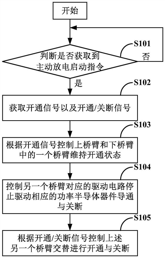
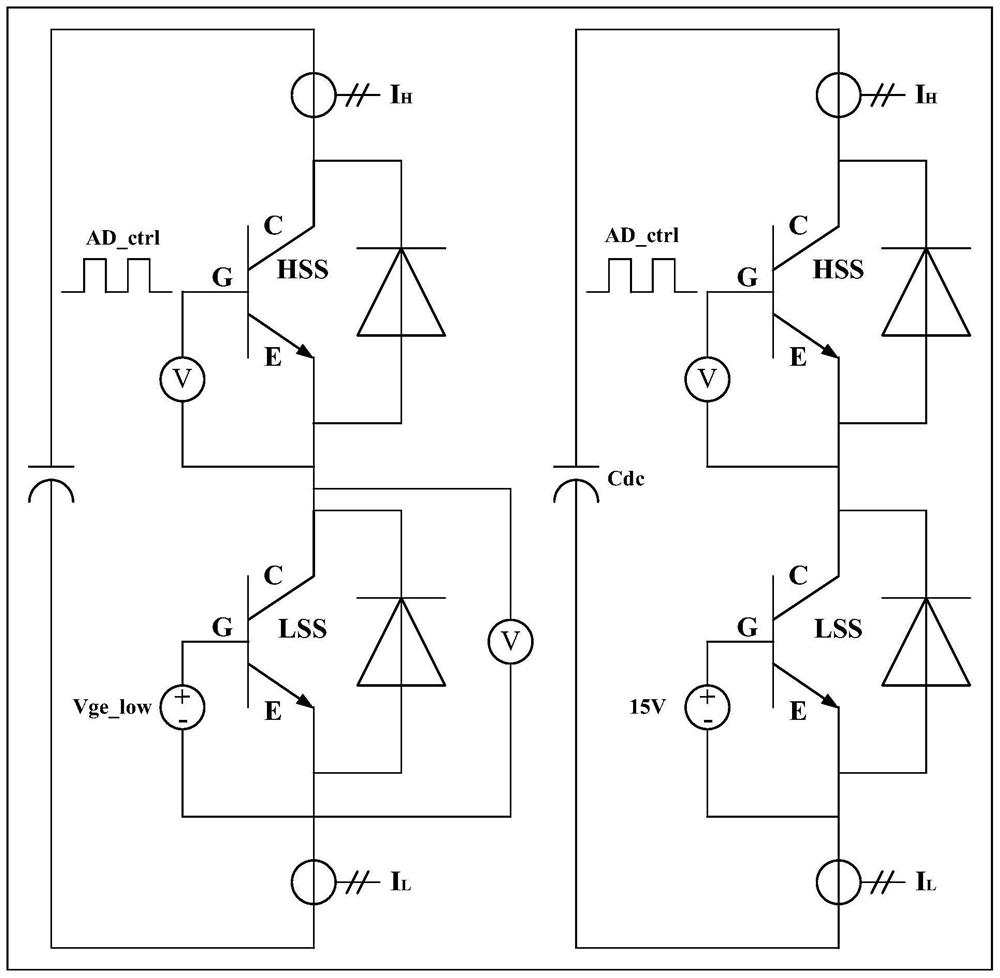
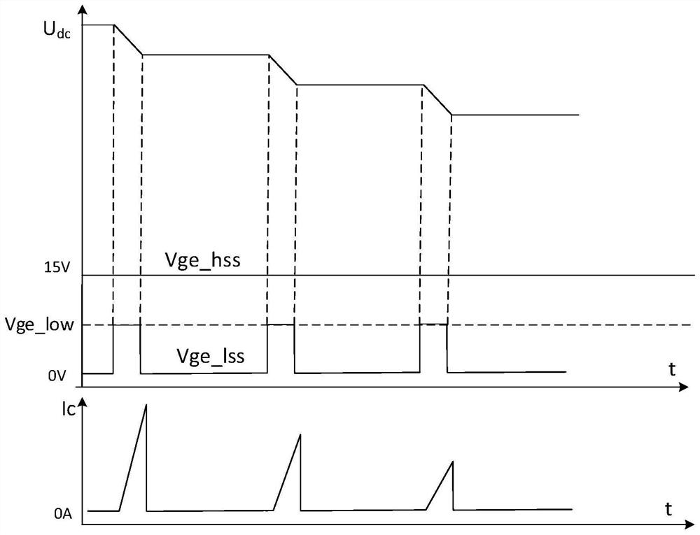
[0210] The active discharge method of the DC bus capacitor in the current power device mainly includes using the discharge resistor or the motor winding to consume the electric energy in the capacitor. This method needs to set up an additional circuit structure and the motor may produce unexpected motor when the discharge is out of control. torque. Based on this, the present invention provides a method to discharge the DC bus capacitor by using the direct connection of the half bridge circuit in the power device to consume electric energy. To effectively control the discharge process.

[0211] The specific process of discharging the DC bus c...


PUM


Abstract

The invention relates to the technical field of power electronics, in particular to a method, system, device and vehicle for discharging bus capacitors used in power devices, and aims to solve the technical problem of how to effectively and reliably actively discharge bus capacitors. For this purpose, the method provided by the present invention mainly includes the following steps: controlling one of the upper bridge arm and the lower bridge arm to maintain an open state, and controlling the other bridge arm of the upper bridge arm and the lower bridge arm to alternately open and close off, and the through current of the half-bridge circuit depends on the gate voltage of the weak open bridge arm. Based on the above steps, there is no need to set up an additional circuit structure in the power device, and the electric energy of the DC bus capacitor can be gradually released by controlling the half-bridge circuit to perform multiple short-time throughs. At the same time, by adjusting the duty ratio of the gate voltage of the power semiconductor device to control the through time of the half-bridge circuit, the problem of runaway discharge can be effectively solved.

Description

technical field [0001] The present invention relates to the technical field of power electronics, in particular to a bus capacitor discharge method, system and device for power devices. Background technique [0002] The electric drive system (Electric Drive System, EDS) of a new energy vehicle usually has a high-capacity bus capacitor (such as a bus capacitor with a value of hundreds of microfarads or more). When the main relay of the power battery is disconnected, there will be more residual charge on the bus capacitor and its capacitor voltage will be equal to the output voltage of the power battery. The output voltage of the power battery is often as high as hundreds of volts (such as between 250V and 450V). In order to avoid the high voltage on the bus capacitor from causing harm to the human body, it is necessary to discharge the bus capacitor immediately after the main relay is disconnected. [0003] The discharge method of bus capacitor mainly includes passive discha...

Claims


Application Information

Patent Timeline
Patent Type & Authority Patents(China)
IPC IPC(8): H02M1/32H02P27/06B60L15/00
CPCB60L15/007H02M1/32H02P27/06H02M1/322Y02T10/64
Inventor 苏谢祖张帆洪文成杜永红路红亮单亮张煜
Owner NIO ANHUI HLDG CO LTD
Why Eureka
Try Eureka