
Wavelength bandwidth allocation method

A bandwidth allocation method and bandwidth allocation technology are applied in the direction of data exchange through path configuration, electrical components, multiplexing system selection devices, etc., which can solve the problems of shortened allocation time and slow transmission speed, and eliminate Unfairness, the effect of increasing the wavelength bandwidth allocation rate

Active Publication Date: 2014-09-10
NIPPON TELEGRAPH & TELEPHONE CORP
View PDF7 Cites 3 Cited by
  • Summary
  • Abstract
  • Description
  • Claims
  • Application Information

AI Technical Summary

Problems solved by technology

However, in the PON network, since the wavelength of the optical signal used for the uplink signal is a single wavelength, if the number of users using the PON network at the same time increases, the allocation time of each user becomes shorter, resulting in slower transmission speed

Method used


Image

  • Wavelength bandwidth allocation method
  • Wavelength bandwidth allocation method
  • Wavelength bandwidth allocation method

Examples


Embodiment Construction

[0041] Embodiments of the present invention will be described with reference to the drawings. The embodiment described below is an example of the present invention, but the present invention is not limited to the following embodiment. In addition, the component parts of the same code|symbol in this specification and drawing represent the same thing.

[0042] (Summary of wavelength bandwidth allocation method)

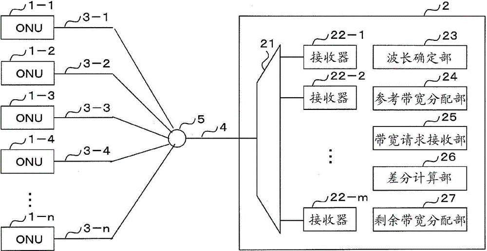
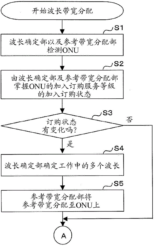
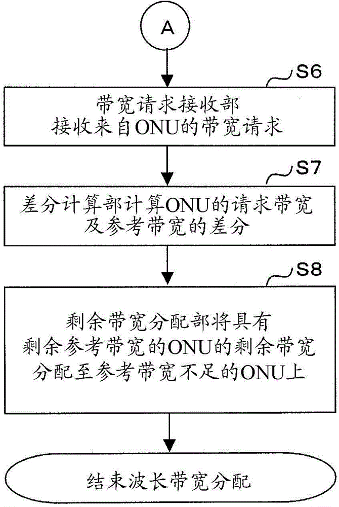
[0043] figure 1 The structure of the PON of the present invention is shown. figure 2 as well as image 3 A flow chart of the wavelength bandwidth allocation method of the present invention is shown.

[0044] PON consists of n (n is a complex number) ONU1-1, 1-2, 1-3, 1-4, ..., 1-n, OLT2, n transmission paths 3-1, 3-2, 3-3, 3 -4, . . . , 3-n, a transmission path 4 and a power divider 5 are formed.

[0045]OLT2 is composed of wavelength filter 21, m (m is a complex number) receivers 22-1, 22-2, ..., 22-m, wavelength determination unit 23, reference bandwidth alloca...


PUM


Abstract

The present invention is a wavelength bandwidth allocation method characterized by including in the given order: a wavelength determination step (S4) for determining a plurality of wavelengths for uplink signals from each ONU to an OLT so as to guarantee a guaranteed bandwidth corresponding to the client service class of each ONU; and a reference bandwidth distribution step (S5) in which the entire bandwidth having the plurality of wavelengths determined in the wavelength determination step (S4) is distributed as reference bandwidth to each ONU in accordance with the client service class of each ONU, and the reference bandwidth of each ONU having the same client service class is made to be the same.

Description

technical field [0001] The invention relates to a wavelength bandwidth allocation method in WDM / TDM-PON. Background technique [0002] With the rapid popularization of the Internet, a large-capacity access service is required. Thereby realizing PON (Passive Optical Network, passive optical network), described PON is the optical transmission system of shared access mode in which the transmission bandwidth of the line is shared by multiple users, and with the reduction of the cost of the device, it can be FTTH (Fiber To The Home, Fiber To The Home) service is provided at a reasonable price. [0003] By realizing the PON as described above, the communication market is continuously developing, but in order to further satisfy the service needs of users, the communication capacity of the PON needs to be increased. However, in the PON network, since the wavelength of the optical signal used for the uplink signal is a single wavelength, if the number of users using the PON network...

Claims


Application Information

Patent Timeline
Patent Type & Authority Applications(China)
IPC IPC(8): H04L12/44
CPCH04J14/0246H04J2203/0098H04Q2011/0086H04J2203/0057H04J14/0252H04Q2011/0084H04Q11/0067H04J14/0247H04J14/0249H04J14/0282H04J14/025
Inventor 玉置真也中村浩崇木村俊二
Owner NIPPON TELEGRAPH & TELEPHONE CORP
Learn More