Image Processing Device

An image processing device and original image technology, applied in image communication, optical observation device, solid-state image signal generator, etc., can solve the problems of image quality deterioration, complex pixel circuit and reading circuit, etc.

Active Publication Date: 2014-09-10
HONDA MOTOR CO LTD
View PDF8 Cites 6 Cited by
  • Summary
  • Abstract
  • Description
  • Claims
  • Application Information

AI Technical Summary

Problems solved by technology

[0006] However, in this method, the pixel circuit and the readout circuit of the imaging element become complicated, and the image quality of the captured ...

Method used


Image

  • Image Processing Device
  • Image Processing Device
  • Image Processing Device

Examples


Embodiment Construction

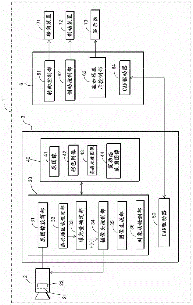
[0042] refer to figure 1 ˜ FIG. 9 illustrate an embodiment of the image processing device of the present invention. refer to figure 1 , the image processing device of the present embodiment includes a camera 2 mounted on a vehicle 1 and an image controller 3 connected to the camera 2 .

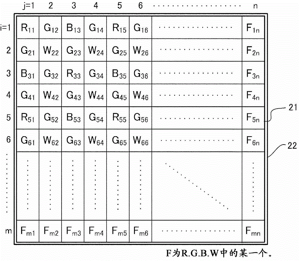
[0043] The camera 2 photographs the surroundings of the vehicle 1 through an imaging element 22 (CCD, CMOS, etc.) equipped with a filter 21 , and outputs the photographed data to the control circuit 30 . The imaging element 22 is composed of m×n photosensitive pixels arranged in a two-dimensional space.

[0044] Referring to (a) in Fig. 2, the filter 21 is configured by (selectively) disposing R (red), G (green), B (blue) ) Formed by any one of the 3 primary color color filters. In addition, as the color filter, other types of color filters (CyMgY complementary color filters, etc.) other than RGB can be used.

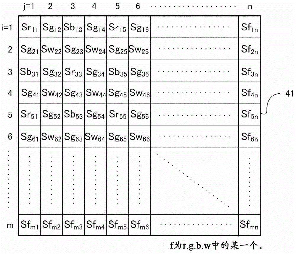
[0045] And, the camera 2 outputs the color scale value data corresponding to t...


PUM


Abstract

An exposure level determination unit (33) determines, for a region of interest in an original image captured by a camera (2) using a first exposure level in a control cycle at a predetermined time point, a second exposure level which is an exposure level for the next control cycle, by calculating a transparent pixel saturation rate which is a ratio of transparent pixels having a saturated gradation value among transparent pixels in the region of interest, and changing the first exposure level according to the transparent pixel saturation rate.

Description

technical field [0001] The present invention relates to an image processing device that processes captured (image) data obtained by an imaging element composed of pixels that receive light through a color filter and pixels that do not receive light through a color filter. Background technique [0002] In the prior art, a method has been proposed in which an imaging element is composed of pixels receiving light through a color filter (color photosensitive pixels) and pixels not receiving light through a color filter (direct photosensitive pixels), and using this The imaging element can improve the sensitivity of a color image (for example, refer to Patent Document 1). [0003] [Patent Document 1] Japanese Invention Patent Laid-Open Publication Special Table No. 2008-507908 [0004] Among the pixels that receive light through the color filter (color sensitive pixel) and the pixels that do not receive light through the color filter (direct sensitive pixel), the direct sensitiv...

Claims


Application Information

Patent Timeline
IPC IPC(8): H04N9/07H04N5/225H04N5/238
CPCG06K9/00798H04N5/2351B60R2300/804B60R1/00H04N5/2355H04N9/045H04N23/71H04N23/73H04N23/741H04N25/133H04N25/135G06V20/588
Inventor 加纳忠彦安达允彦
Owner HONDA MOTOR CO LTD
Why Eureka
Try Eureka