

Core drawing mechanism
A frame and mandrel technology, which is applied in the field of core pulling mechanism of cold-formed special-shaped pipes, can solve the problems of long time, high labor intensity, mandrel damage, etc., and achieve the effects of smooth movement, improved automation, and reduced volume.
- Summary
- Abstract
- Description
- Claims
- Application Information
AI Technical Summary
Problems solved by technology
Method used
Image

Examples
Embodiment Construction
[0027] The present invention will be further described in detail below in conjunction with the accompanying drawings and embodiments.
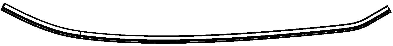
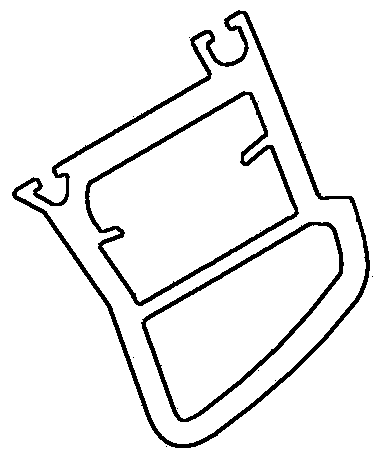
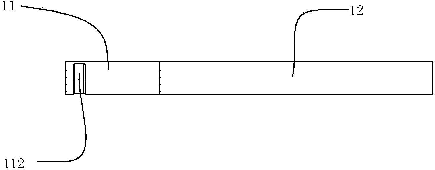
[0028] Such as Figure 2a-2c Shown is a schematic view of the mandrel 1 used in the present invention, the mandrel 1 includes a core 11 and a core 12, the core 11 is located at one end of the core 12, and the width of the core 11 on a horizontal plane is greater than that of the core 12 in width, wherein the core 12 is made of soft material and inserted into the cavity of the special-shaped tube 10 to avoid deformation of the inner cavity of the product during cold bending. Such as Figure 2b As shown, it is a top view of the core rod 1, one end of the core head 11 is provided with an avoidance groove 111 along its thickness direction along its length direction, and the escape groove 111 does not extend to the other end of the core head 11. One end of head 11 is divided into left and right sides, as Figure 2b As shown in the top view, the ...
PUM
 Abstract
Description
Claims
Application Information