Inflating valve wrench
A valve, wrench rod technology, applied in the direction of wrenches, manufacturing tools, wrenches, etc., can solve the problems of slow installation speed, time-consuming and laborious, and achieve the effect of fast installation speed, wide application range and reasonable structure
Inactive Publication Date: 2014-09-17
YIZHENG SHENDI IND DEV
View PDF0 Cites 0 Cited by
- Summary
- Abstract
- Description
- Claims
- Application Information
AI Technical Summary
Problems solved by technology
The installation speed of this tool is relatively slow, and the valve installation cap needs to be removed, which is time-consuming and labor-intensive
Method used
View moreImage
Smart ImageViewing Examples

Examples
Embodiment Construction
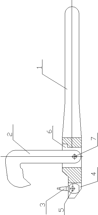
[0007] Such as figure 1 As shown, the present invention includes a wrench rod 1, an "L"-shaped movable claw 2, and a valve movable pin 3. One end of the wrench rod 1 is provided with a first installation groove 4, and the valve movable pin 3 is arranged in the first installation groove 4. and is hinged with the wrench lever 1 through the first pin 5; the second installation groove 6 is set on the side of the wrench lever 1 close to the first installation groove 4, and one end of the "L"-shaped movable claw 2 is set on the second installation groove. In the groove 6, and through the second pin 7 and wrench lever 1 hinge, the free end of "L" shaped movable claw 2 is olecranon shape.
Login to View More PUM
 Abstract
The invention provides an inflating valve wrench, and relates to the technical field of design of auxiliary tools. The inflating valve wrench comprises a wrench rod, an L-shaped movable clamping jaw and an inflating valve movable pin, wherein one end of the wrench rod is provided with a first mounting groove, the inflating valve movable pin is arranged in the first mounting groove, and is hinged to the wrench rod through a first pin, one side, near the first mounting groove, of the wrench rod is provided with a second mounting groove, one end of the L-shaped movable clamping jaw is arranged in the second mounting groove, and is hinged to the wrench rod through a second pin, and the free end of the L-shaped movable clamping jaw is in an eagle beak shape. The inflating valve wrench has the advantages that the structure is reasonable, the detachment of an inflating valve cap is not needed, and the inflating valve wrench is directly installed and is fully inflated after installation, and is suitable for the installation of the inflating valve of the sub-assembly line of tire assemblies.
Description
technical field [0001] The invention relates to the technical field of auxiliary tool design, in particular to a valve wrench applied to a tire assembly. Background technique [0002] The existing product adopts the principle of a pull rod, and the thread on the installation tool is rotated to the thread on the valve, and then the valve is installed in place through the principle of tension. The installation speed of this tool is relatively slow, and it is time-consuming and labor-intensive to remove the valve installation cap. Contents of the invention [0003] The object of the present invention is to provide a time-saving and labor-saving valve wrench aiming at the above defects. [0004] The present invention includes a wrench rod, an "L" shaped movable claw, and a valve movable pin. A first installation groove is arranged at one end of the wrench rod, and the valve movable pin is arranged in the first installation groove, and passes through the first installation gro...
Claims
Login to View More Application Information
Patent Timeline
 IPC IPC(8): B25B13/48
CPCB25B13/48
Inventor 曾勇周俊宋爱宏张小虎
Owner YIZHENG SHENDI IND DEV