Mining roadway frame style advanced support bracket

A technology of advanced support and mining roadway, which is applied to mine roof support, mining equipment, earthwork drilling and other directions, can solve the problems of easily damaged roadway roof bolt support, small support area, low operation efficiency, etc. Compact, supportive and mobile stable, easy-to-operate effect

Inactive Publication Date: 2014-09-17
SHENYANG TIAN AN TECH CO LTD
View PDF13 Cites 3 Cited by
  • Summary
  • Abstract
  • Description
  • Claims
  • Application Information

AI Technical Summary

Problems solved by technology

[0007] The purpose of the present invention is to provide a frame-type advanced support bracket for mining roadway, which solves the problems in the prior art such as small support area, easy damage to the bolt support at the top of the roadway, slow frame movement, cumbersome operation, and low operating efficiency. Its design is reasonable, compact in structure, small in roadway space, easy to operate, stable in support and movement, safe and reliable. While ensuring the safe pedestrian space in the roadway, it can realize the alignment of the roadway roof according to different geological conditions and roadway section shapes. The mechanized advanced support of continuous support can significantly improve the support quality and the production efficiency of coal mining face

Method used


Image

  • Mining roadway frame style advanced support bracket
  • Mining roadway frame style advanced support bracket
  • Mining roadway frame style advanced support bracket

Examples


Embodiment Construction

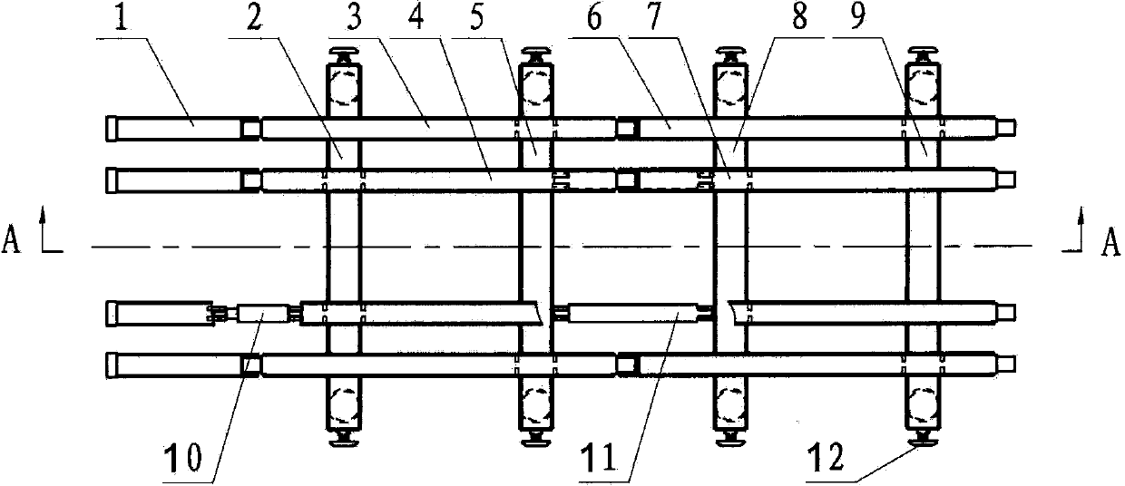
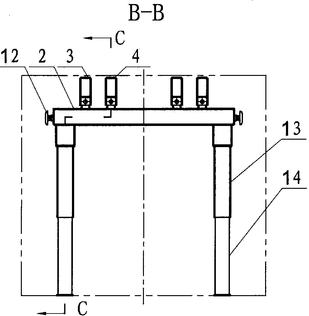
[0020] according to Figure 1~6 The specific structure of the present invention will be described in detail. The mining roadway frame-type advance support bracket includes components such as crossbeams assembled into frames, along beams, and hydraulic columns 14 as supports hinged at the bottom of the crossbeams. The frame is composed of two sets of integral main frames and auxiliary frames which move synchronously respectively.

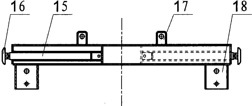
[0021] The main frame includes components such as the main front beam 5, the main rear beam 9, the hydraulic column 14, the main front beam 3 and the main rear beam 6. The main front crossbeam 5 and the main rear crossbeam 9 are provided with an upper connecting seat 17 and a lower connecting seat 18 respectively, and the bottoms of the main frontal beam 3 and the main rearward beam 6 are respectively provided with connecting ear plates 19 . Piston rod guard cover 13 tops that are hinged with the piston rod end of hydraulic column 14 tops are hinge...


PUM


Abstract

A mining roadway frame style advanced support bracket solves the problems that in the prior art, a support area is small, an anchor rod support on the top of a roadway is prone to being damaged, a bracket is slow to move, operation is complex and work efficiency is low. The mining roadway frame style advanced support bracket comprises beams, longitudinal beams and hydraulic upright columns hinged to the bottoms of the beams and serving as a support, wherein the beams, the longitudinal beams and the hydraulic upright columns are assembled to form a frame. The bracket is technically characterized in that the frame is composed of an overall main frame body and an auxiliary frame body, and the overall main frame body and the auxiliary frame body move synchronously; a frame moving hydraulic cylinder hinged between a main front beam of the main frame body and an auxiliary rear beam of the auxiliary frame body drives the main frame body or the auxiliary frame body to move synchronously as a whole; the two ends of the main front beam and a main rear beam and the two ends of an auxiliary front beam and the auxiliary rear beam are respectively connected with lateral telescopic mechanisms in a hinged mode. The mining roadway frame style advanced support bracket is reasonable in design, compact in structure, easy and convenient to operate, stable in supporting and moving and safe and reliable, occupies little space in the roadway, can achieve mechanical advanced support for continuously supporting a roadway top plate according to different geological conditions and roadway sectional shapes, and remarkably improves support quality and production efficiency of a coal mining working face.

Description

technical field [0001] The invention relates to a roadway advance support device for safe operation of a mining face, in particular to a mining roadway frame-type advance support bracket that can move forward with the advance of mining in the mining face. It belongs to the field of mining machinery manufacturing and application. Background technique [0002] In the roadway of modern comprehensive mechanized mining operations, with the continuous advancement of the coal mining face, the pressure of the leading section of the mining roadway moves forward, so it is necessary to strengthen the support at the leading section of the working face. The advance support of the roadway is to prevent the deformation, movement and damage of the surrounding rock of the roadway caused by the superposition of the advanced bearing pressure of the working face and the bearing pressure along the inclined direction. The support method used is to ensure the normal operation and Ventilation, so ...

Claims


Application Information

Patent Timeline
IPC IPC(8): E21D23/04
Inventor 曹伟滕飞胡宇金灿东王荣亮
Owner SHENYANG TIAN AN TECH CO LTD
Why Eureka
Try Eureka