Locking cylinder structure with cushioning at the end of stroke

A technology for locking cylinders and strokes, which is applied in the direction of fluid pressure actuation devices, etc., which can solve the problems of low cylinder locking speed and affecting the important performance of servo tool holders - tool change speed, large cylinder locking force, etc.

Active Publication Date: 2016-01-13
CHANGZHOU XINSHU MASCH TOOL CNC EQUIP CO LTD
View PDF8 Cites 0 Cited by
  • Summary
  • Abstract
  • Description
  • Claims
  • Application Information

AI Technical Summary

Problems solved by technology

[0002] At present, the working principle of the servo tool post is: the servo motor is used to rotate, the triple toothed disc is indexed and positioned, and the short-stroke cylinder is locked. Due to the error between the servo tool post position and the toothed disc positioning, " "Positive position" action, and the locking force of the oil cylinder is relatively large, and the impact is large when locking; although the throttle valve speed regulation can achieve the buffering effect, the locking speed of the oil cylinder is significantly reduced, which seriously affects the important performance of the servo tool post-replacement knife speed

Method used


Image

  • Locking cylinder structure with cushioning at the end of stroke

Examples


Embodiment Construction

[0012] In order to make the content of the present invention more clearly understood, the present invention will be further described in detail below based on specific embodiments and in conjunction with the accompanying drawings.

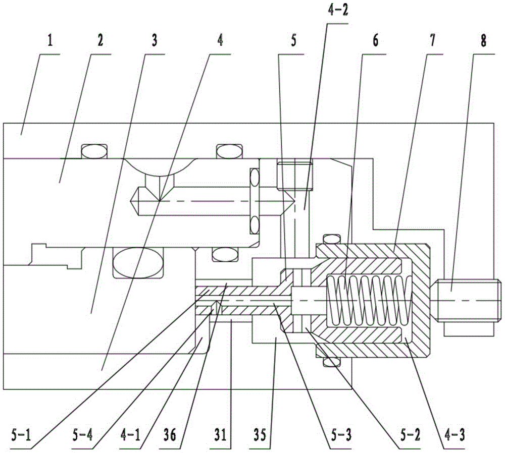
[0013] Such as figure 1 As shown, a locking cylinder structure with stroke end cushioning includes a cylinder seat 4, a cushion valve sleeve 7, a cushion valve core 5, a piston 3 and a spring 6, and the cylinder seat 4 has an oil supply channel and a cylinder chamber 4-1. The buffer valve sleeve 7 is installed on the cylinder seat 4, the piston 3 is located in the cylinder cavity 4-1, the buffer valve core 5 is slidingly fitted in the buffer valve sleeve 7, and the spring 6 is arranged on one end of the buffer valve core 5 and the buffer valve sleeve 7 Between, the other end of the buffer spool 5 extends into the cylinder chamber 4-1, and a large flow passage and a small flow buffer passage for supplying oil to the cylinder chamber 4-1 are arranged...


PUM


Abstract

The invention discloses a locking oil cylinder structure with a stroke tail end buffered. The locking oil cylinder structure comprises an oil cylinder seat, a buffer valve sleeve, a buffer valve element, a piston and a spring, the oil cylinder seat is provided with an oil supply channel and an oil cylinder cavity, the buffer valve sleeve is arranged on the oil cylinder seat, the piston is located in the oil cylinder cavity, the buffer valve element is arranged in the buffer valve sleeve in a sliding and matching mode, the spring is arranged between one end of the buffer valve element and the buffer valve sleeve, the other end of the buffer valve element stretches into the oil cylinder cavity, a large-flow channel and a small-flow buffer channel which are used for supplying oil to the oil cylinder cavity are arranged between the oil supply channel and the oil cylinder cavity, the large-flow channel is arranged between the oil cylinder seat and the buffer valve element, and the small-flow buffer channel is arranged on the buffer valve element. When the piston reaches a certain stroke, the buffer valve element is matched with the oil cylinder seat under the action of the spring to plug the large-flow channel, and oil passes through the small-flow buffer channel from the oil supply channel and flows into the oil cylinder cavity. The locking oil cylinder structure can achieve the quick locking function, and has the buffer function in the later locking period, and therefore tool changing speed can be improved, and meanwhile the impact phenomenon is avoided.

Description

technical field [0001] The invention relates to a locking oil cylinder structure buffered at the stroke end, and belongs to the technical field of CNC machine tool servo tool holders. Background technique [0002] At present, the working principle of the servo tool post is: the servo motor is used for indexing, the triple toothed disc is indexed and positioned, and the short-stroke cylinder is locked. Due to the error between the servo tool post position and the toothed disc positioning, " "Positive position" action, and the locking force of the oil cylinder is relatively large, and the impact is large when locking; although the throttle valve speed regulation can achieve the buffering effect, the locking speed of the oil cylinder is significantly reduced, which seriously affects the important performance of the servo tool post-replacement knife speed. Contents of the invention [0003] The technical problem to be solved by the present invention is to overcome the defects...

Claims


Application Information

Patent Timeline
Patent Type & Authority Patents(China)
IPC IPC(8): F15B15/22F15B15/14
Inventor 刘新东龚国全
Owner CHANGZHOU XINSHU MASCH TOOL CNC EQUIP CO LTD
Why Eureka
Try Eureka