Redundant seal pipeline connector

A sealed pipe, redundant technology, applied in the direction of pipe joints, pipes/pipe joints/fittings, fluid tightness testing, etc., can solve the problem of reduced sealing effect of pipeline sealing structure, complex detection devices and detection procedures, and impossibility of sealing Leakage and other issues

Active Publication Date: 2014-09-17
BEIJING INST OF SPACE LAUNCH TECH +1
View PDF5 Cites 13 Cited by
  • Summary
  • Abstract
  • Description
  • Claims
  • Application Information

AI Technical Summary

Problems solved by technology

[0002] Some low-temperature filling systems such as automobile gas filling stations and some normal-temperature flammable, explosive or toxic gas filling systems have relatively high requirements for the sealing of the pipeline interface. In some low-temperature filling systems, the low-temperature medium is due to Its boiling point temperature is low, so that the metal materials and non-metallic materials it contacts are prone to large cold shrinkage. In the case of low-temperature cold shrinkage of pipeline materials, the sealing effect of the existing pipeline sealing structure is greatly reduced or even Can lead to sealing failure; In addition, in the prior art, when leaking occurs at the sealing structure in the sealing system, the existing sealing leak detection device is used to detect it is not convenient and fast enough, and the detection device and detection device in the prior art The program is also relatively complicated, and it is impossible to carry out online detection of seal leakage
In addition, it is impossible or inconvenient for personnel to perform seal leak detection of pipeline joints in confined spaces and narrow spaces

Method used


Image

  • Redundant seal pipeline connector
  • Redundant seal pipeline connector
  • Redundant seal pipeline connector

Examples


Embodiment Construction

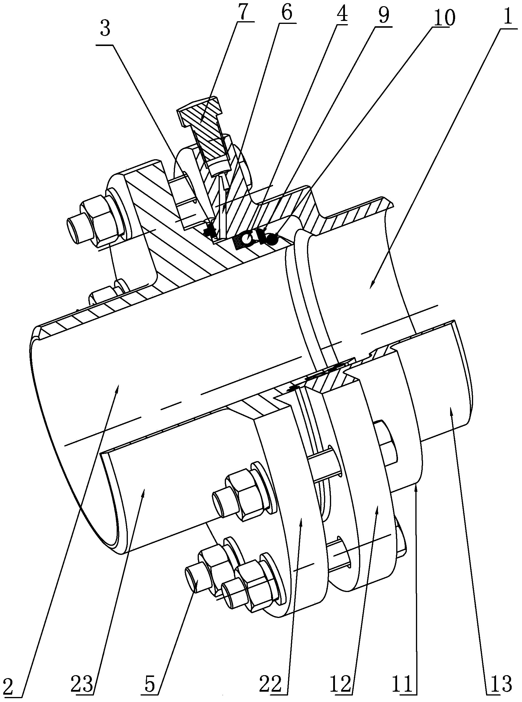
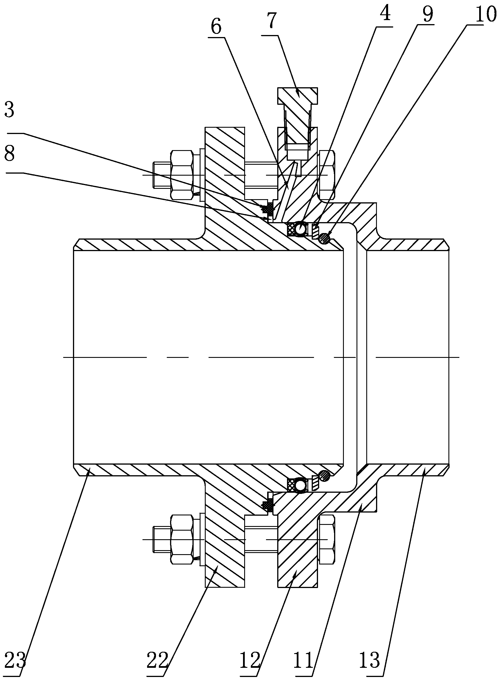
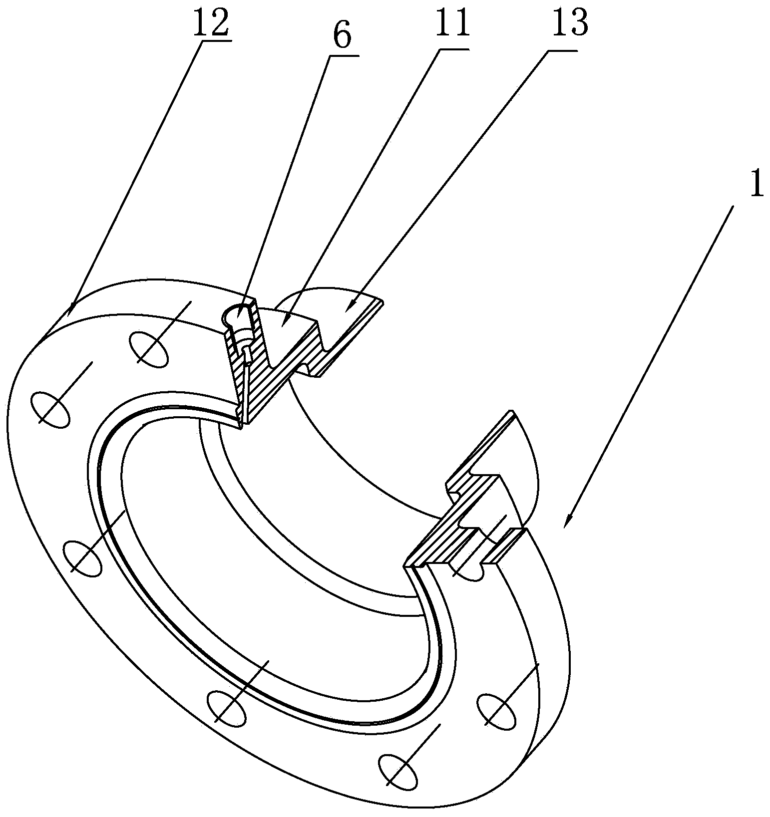
[0021] Such as figure 1 , figure 2 , image 3 with Figure 4 As shown, the redundant sealing pipeline joint of the present invention includes a seal seat 1, a seal cone 2, an end face seal 3, a radial seal 4 and a fastener 5, and the seal seat 1 includes a first axial protrusion 11, a first The annular flange 12 and the first welding end 13, the first axial protrusion 11, the first annular flange 12 and the first welding end 13 are integrally made, and the sealing cone 2 includes the second axial protrusion 21, The second annular flange 22 and the second welding end 23, the second axial protrusion 21, the second annular flange 22 and the second welding end 23 are integrally made, and the fastener 5 is installed on the first annular On the flange 12 and the second annular flange 22, the sealing seat 1 and the sealing cone 2 are fixedly connected by fasteners 5, there are several fasteners 5, and the fasteners 5 are installed on the first annular flange 12 On the second ann...


PUM


Abstract

The invention relates to a pipeline connector used for a filling system with higher sealing requirements, and aims to provide a redundant seal pipeline connector which has a simple structure, is reliable to seal, simple and convenient to operate, and can carry out the on-line detection on the sealing effect of the pipeline connector at the same time. The redundant seal pipeline connector comprises a seal receptacle, a seal cone, end surface sealing pieces, radial sealing pieces and fastening pieces, wherein the seal receptacle comprises a first axial bulge, a first annular flange and a first welding end, which are manufactured integrally; the seal cone comprises a second axial bulge, a second annular flange and a second welding end, which are manufactured integrally; the end surface of the second axial bulge is in butt joint with the end surface of the first annular flange; the end surface sealing pieces are positioned on the butt-joint matched surfaces; the front end of the second axial bulge is sleeved with the first annular flange; the radial sealing pieces are positioned in the radial matched surfaces; the fastening pieces are used for fixedly connecting the seal receptacle with the seal cone; a pressure measuring channel is arranged on the first annular flange; an air outlet end port of the pressure measuring channel is connected with a seal cap.

Description

technical field [0001] The invention relates to a pipeline sealing structure, in particular to a pipeline joint used in a filling system with high sealing requirements. Background technique [0002] Some low-temperature filling systems such as automobile gas filling stations and some normal-temperature flammable, explosive or toxic gas filling systems have relatively high requirements for the sealing of the pipeline interface. In some low-temperature filling systems, the low-temperature medium is due to Its boiling point temperature is low, so that the metal materials and non-metallic materials it contacts are prone to large cold shrinkage. In the case of low-temperature cold shrinkage of pipeline materials, the sealing effect of the existing pipeline sealing structure is greatly reduced or even Can lead to sealing failure; In addition, in the prior art, when leaking occurs at the sealing structure in the sealing system, the existing sealing leak detection device is used to ...

Claims


Application Information

Patent Timeline
Patent Type & Authority Applications(China)
IPC IPC(8): F16L23/032F16L23/18G01M3/04
CPCF16L23/032F16L23/18F16L2201/30F17D5/02G01M3/085
Inventor 张振华丁大江唐强杨俊恒王自力王立张波白文龙
Owner BEIJING INST OF SPACE LAUNCH TECH
Why Eureka
Try Eureka