
A Compensation Device for Optical Fiber Nonlinearity and Dispersion Effects with a Resonant Cavity

A dispersion effect and compensation device technology, applied in optical fiber transmission, elimination of distortion/dispersion, electromagnetic wave transmission system, etc., can solve problems such as large amount of calculation, high complexity, inability to realize nonlinear and dispersion compensation, etc., and achieve nonlinear enhancement , small size, enhanced effect of non-linear characteristics

Inactive Publication Date: 2016-08-24
TONGJI UNIV
View PDF3 Cites 0 Cited by
  • Summary
  • Abstract
  • Description
  • Claims
  • Application Information

AI Technical Summary

Problems solved by technology

Although this type of method can better compensate for the dispersion and nonlinear effects of optical fibers, for ultra-high-speed, ultra-long-distance optical fiber transmission, this method has a large amount of calculation and high complexity, and can only be processed offline. Real-time nonlinear and dispersion compensation cannot be realized

Method used


Image

  • A Compensation Device for Optical Fiber Nonlinearity and Dispersion Effects with a Resonant Cavity
  • A Compensation Device for Optical Fiber Nonlinearity and Dispersion Effects with a Resonant Cavity
  • A Compensation Device for Optical Fiber Nonlinearity and Dispersion Effects with a Resonant Cavity

Examples


Embodiment

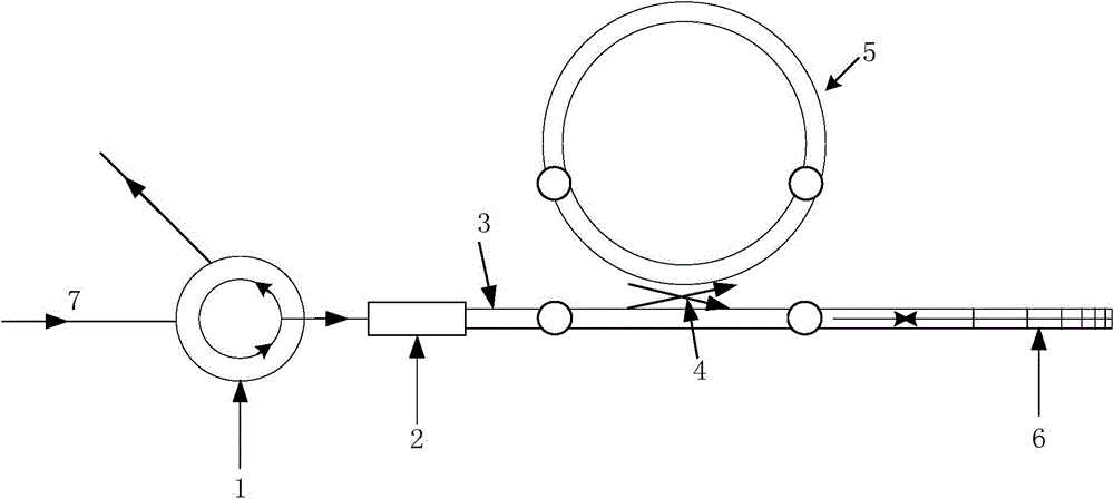
[0029] like figure 1 As shown, a fiber optic nonlinearity and dispersion effect compensation device with a resonant cavity includes an optical fiber 7, a circulator 1, a fiber-waveguide coupler 2, a silicon waveguide 3, a waveguide coupler 4, a resonant cavity 5 and a chirped grating 6. The optical fiber 7, circulator 1, fiber-waveguide coupler 2, silicon waveguide 3 and chirped grating 6 are sequentially connected, and the waveguide coupler 4 is arranged between the silicon waveguide 3 and the resonant cavity 5;

[0030] The resonant cavity 5 uses its nonlinear optical characteristics to generate a nonlinear phase shift to compensate the nonlinear effect of the optical fiber; the grating period of the chirped grating 6 changes along the axial direction, which can make incident light of various wavelengths Reflecting at different positions produces a large group delay slope and compensates for the dispersion effect of the fiber.

[0031] The resonant cavity 5 utilizes its no...


PUM


Abstract

The invention relates to an optical fiber nonlinear and dispersion effect compensation device with a resonant cavity, which includes an optical fiber, and the device also includes a circulator, a fiber-waveguide coupler, a silicon waveguide, a waveguide coupler, a resonant cavity and a chirped grating. The optical fiber, the circulator, the fiber-waveguide coupler, the silicon waveguide and the chirped grating are sequentially connected, and the waveguide coupler is arranged between the silicon waveguide and the resonant cavity, and the resonant cavity utilizes its nonlinear optical characteristics A nonlinear phase shift is generated to compensate the nonlinear effect of the optical fiber; the grating period of the chirped grating changes along the axial direction, which can reflect incident light of various wavelengths at different positions and generate a large group delay slope , to compensate for the dispersion effect of the fiber. Compared with the prior art, the invention has the advantages of real-time compensation, small volume, easy expansion and the like.

Description

technical field [0001] The invention relates to a compensation device for optical fiber nonlinearity and dispersion effect, in particular to a compensation device for optical fiber nonlinearity and dispersion effect with a resonant cavity. Background technique [0002] like figure 2 As shown, the optical fiber communication system is mainly composed of three parts: transmitter, optical fiber transmission and receiver. The transmitter includes a light source and a modulator. The signal sent by the transmitter is transmitted through N-segment optical fiber links, and an amplifier is required for each transmission segment. The signal is amplified to compensate for the attenuation in the transmission process, and the signal transmitted through the optical fiber is received by the receiver. The function of the receiver is to compensate the dispersion and nonlinear effects of the received signal, and resolve it through the coherent demodulation module. to restore the original dig...

Claims


Application Information

Patent Timeline
Patent Type & Authority Patents(China)
IPC IPC(8): H04B10/2513H04B10/2543
Inventor 周俊鹤操砚茹
Owner TONGJI UNIV
Learn More