Rotor assembly

A rotor and component technology, applied in the direction of electric components, magnetic circuit rotating parts, electrical components, etc., can solve the problems of no performance, high cost, excessive generator structure, etc., and achieve the effect of logistics improvement

Active Publication Date: 2014-09-17
GE RENEWABLE TECH WIND BV
View PDF6 Cites 5 Cited by
  • Summary
  • Abstract
  • Description
  • Claims
  • Application Information

AI Technical Summary

Problems solved by technology

[0007] Although modular generators may be advantageous for transport and maintenance or repair operations, the prior art solutions described above have disadvantages: In order to ensure that the generator has sufficient rigidity to withstand the operating conditions, the generator structure is too large
This undesirably leads to higher cost, but not better performance

Method used


Image

  • Rotor assembly
  • Rotor assembly
  • Rotor assembly

Examples


Embodiment Construction

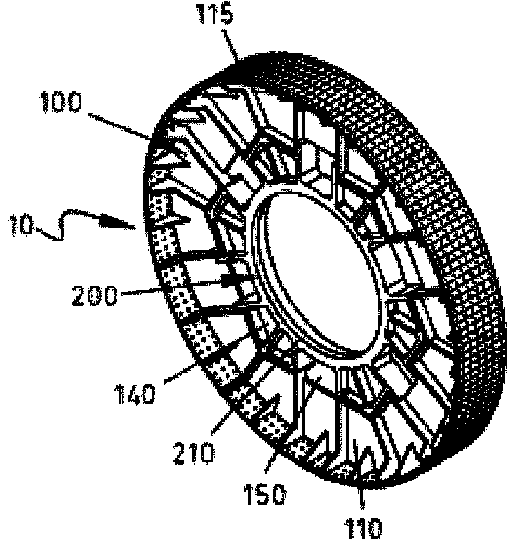
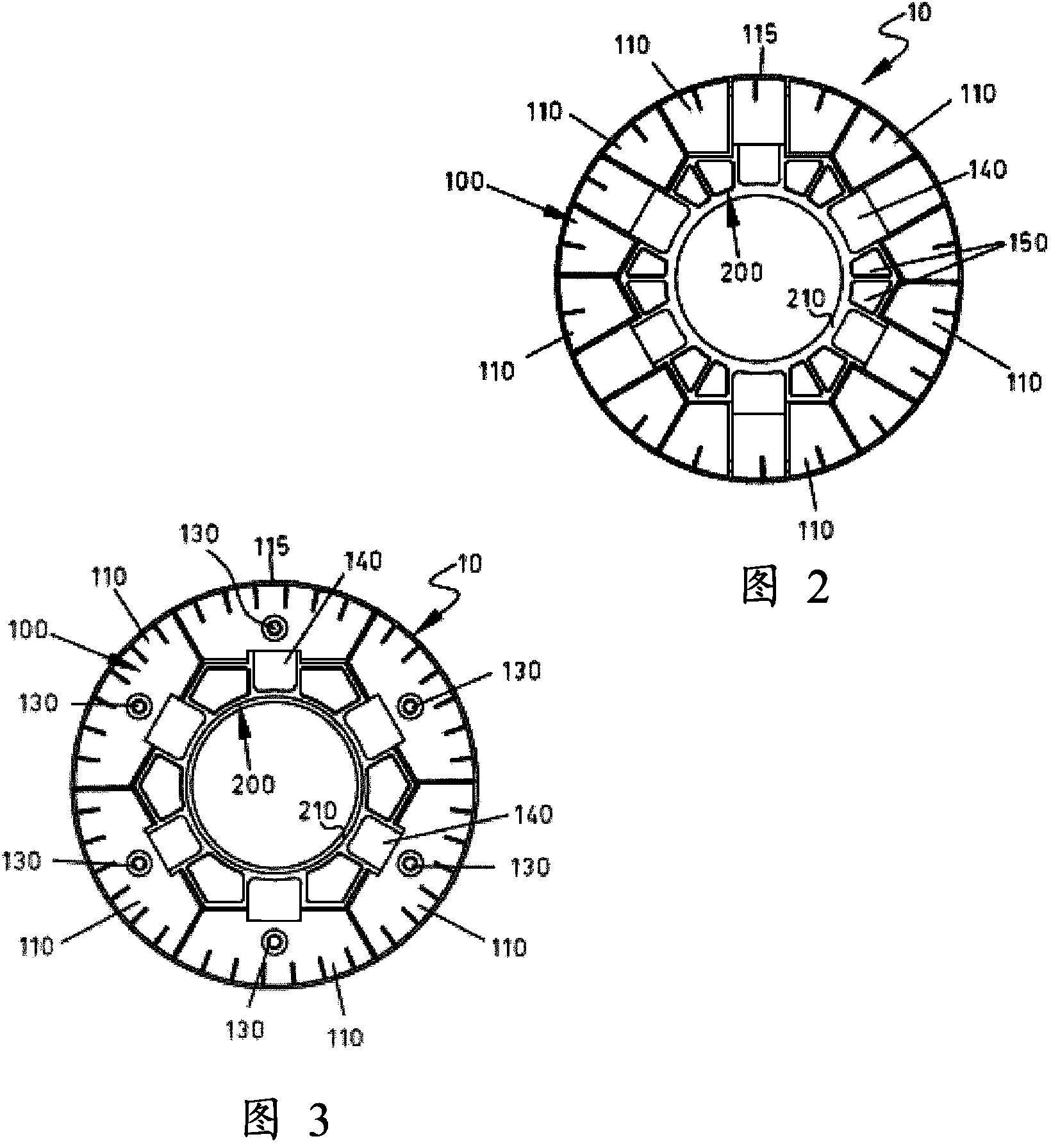
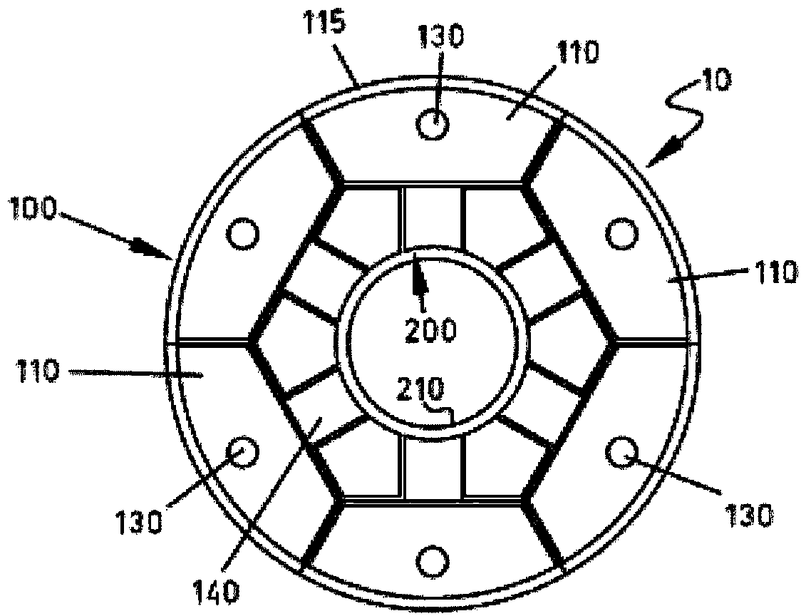
[0030] The figures show different embodiments of rotor assemblies suitable for direct synchronous wind turbine generators. The rotor assembly is generally indicated by the reference numeral 10 throughout the figures. In the respective drawings, the same reference numerals denote the same parts.

[0031] Such as Figure 7 and Figure 8 As shown, the rotor assembly 10 is rotatable relative to the stator assembly 300 via suitable bearings 310 .

[0032] As a non-limiting example in Figure 1-5 The embodiment of the rotor assembly 10 shown in includes six rotor segments 110 . Other embodiments of the rotor assembly 10 may also have other different numbers of rotor segments 110 as desired. For example, Figure 6 The illustrated embodiment of the rotor assembly 10 includes four rotor segments 110 .

[0033] Such as Figure 1-6 As shown, rotor segments 110 form modular rotor structure 100 . Dividing the rotor structure 100 of the rotor assembly 10 into rotor segments 110 fac...


PUM


Abstract

The rotor assembly (10) comprises a number of rotor segments (110) forming a rotor structure (100) and a central structure (200) connected to the rotor structure (100) and at least partially arranged between at least two of the rotor segments (110), for example surrounded by the rotor structure. A wind turbine generator comprising a stator assembly (300) and said rotor assembly (10) and a wind turbine comprising such a generator are also provided.

Description

[0001] This application claims priority to European Patent Application EP11382029, filed January 27, 2012, and US Provisional Patent Application No. 61 / 616,105, filed March 27, 2012. [0002] A rotor assembly as defined in the preamble of claim 1 is disclosed herein. A wind turbine generator comprising a rotor assembly as defined in the preamble of claim 8 is also disclosed herein. A wind turbine comprising a generator as defined in the preamble of claim 9 is also disclosed herein. Background technique [0003] Direct drive wind turbines are known in which the gearbox is replaced by a multi-pole generator, which is usually arranged between the generator and the main shaft of the wind turbine. This type of gearless wind turbine does not use any gearbox as the wind rotor is directly connected to the rotor of the wind turbine. Therefore, multi-pole generators are also referred to as direct-drive generators. The direct drive generator can be, for example, a synchronous generato...

Claims


Application Information

Patent Timeline
Patent Type & Authority Applications(China)
IPC IPC(8): H02K1/30H02K7/18
CPCH02K7/1838H02K1/27Y02E10/725H02K1/30Y02E10/72
Inventor 皮勒·克塔达阿科斯塔
Owner GE RENEWABLE TECH WIND BV
Why Eureka
Try Eureka