
Guide rail type cylinder bottom sludge discharge machine with vertically arranged transmission gear

A technology for installing guide rails and transmission devices, which is applied in the direction of cleaning hollow objects, cleaning methods and appliances, chemical instruments and methods, etc. It can solve the problems of inability to remove sludge, high equipment cost, and the position of the power reversing head, so as to solve the problem of decontamination Dead angle problem, cost reduction effect

Inactive Publication Date: 2014-09-24
抚顺市明尧石油机械有限公司
View PDF7 Cites 0 Cited by
  • Summary
  • Abstract
  • Description
  • Claims
  • Application Information

AI Technical Summary

Problems solved by technology

[0004] The purpose of the present invention is to solve the problem that the Chinese patent "universal joint rail type tank bottom sludge discharger", the patent number, has relatively high equipment cost and the sludge at the position of the power reversing head cannot be removed, and proposes a "transmission The technical scheme of "vertical installation guide rail type tank bottom mud discharger"

Method used


Image

  • Guide rail type cylinder bottom sludge discharge machine with vertically arranged transmission gear
  • Guide rail type cylinder bottom sludge discharge machine with vertically arranged transmission gear

Examples


Embodiment

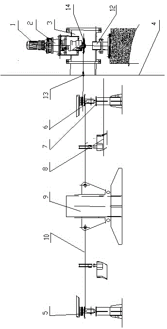
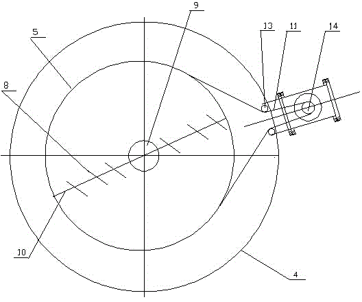
[0015] The transmission device is vertically installed guide rail type tank bottom mud discharger, including a motor 1, a reducer 2, a ring beam 5, a drag beam 10, a central shaft assembly 9 and a scraper head 8, the upper part of the reducer and the tee 3 Port connection, the inner horizontal port of the tee 3 is connected to the flange of the tank wall 4, the outer horizontal port of the tee 3 is closed, the tee 3 is fixed on the support 12, the reducer 2 passes through the working sprocket 14 and the chain 11 The tank wall flange is connected with the ring beam 5. A tensioner 11 is provided at the place where the connecting rod connecting the tee 3 and the ring beam 5 passes through the tank wall 4 . The said ring beam 5 is connected with the drag beam 10, the drag beam 10 bottom is provided with a scraper 8, one end of the drag beam 10 is fixed on the drum of the central shaft assembly 9, and the other end is connected with the ring beam 5. A scraping head is provided at ...


PUM


Abstract

The invention belongs to the technology of sludge discharging at the cylinder bottom of a sewage treating cylinder, and particularly relates to a guide rail type cylinder bottom sludge discharge machine with a vertically arranged transmission gear. The guide rail type cylinder bottom sludge discharge machine comprises a motor, a speed reducer, a ring beam, a dragging beam, a central shaft component and a scraping head, wherein the ring beam is connected with the dragging beam, the lower part of the dragging beam is provided with the scraping head, one end of the dragging beam is fixed on a drum of the central shaft component, the other end of the dragging beam is connected with the ring beam, the lower surface of the ring beam is fixedly provided with a carrier roller which is located above a guide rail, and the guide rail is fixed on the bottom of the cylinder bottom through a support. The guide rail type cylinder bottom sludge discharge machine is characterized in that the speed reducer is connected with the upper end opening of a tee, an inner horizontal end opening of the tee is connected with a cylinder wall flange, the outer horizontal end opening of the tee is closed, the tee is fixed on the support, and the speed reducer is connected with the ring beam through a work chain wheel and a chain by passing by the cylinder wall flange. Two parts, namely, a universal joint and a power reversing head are omitted in the machine, the cost is lowered obviously, and the problem of sludge cleaning dead corners in the cylinder bottom is solved.

Description

technical field [0001] The invention belongs to the sludge discharge technology at the bottom of a sewage treatment tank, in particular to a vertically installed guide rail type tank bottom sludge discharger for a sewage treatment tank, which is used for removing sludge deposited at the bottom of a sewage treatment tank. Background technique [0002] The Chinese patent "Guide rail type tank bottom mud discharger", patent number 201410257914.6, proposes a technical solution to solve the problem of the Chinese patent "Tank bottom mud discharger", patent number 200720012410.3. When scraping mud, the bracket near the tank wall will It is lifted up, which affects the effect of scraping mud. However, when this patented device is working, the sludge at the bottom of the tank acts on the scraping head to generate an upward force, causing the ring beam to also be subjected to an upward force. The ring beam is connected to the power reversing head, and the power reversing head is tran...

Claims


Application Information

Patent Timeline
Patent Type & Authority Applications(China)
IPC IPC(8): B08B9/087
CPCB08B9/087
Inventor 唐艳明
Owner 抚顺市明尧石油机械有限公司
Learn More