Drying room with movable air supply system

An air supply system and drying room technology, applied in the field of drying rooms, can solve the problems of uneven air volume in the drying room and dead ends of material ventilation, and achieve the effects of avoiding dead ends of ventilation, uniform air volume and improving drying efficiency.

Inactive Publication Date: 2014-09-24
盐城江跃机械制造有限公司
View PDF10 Cites 15 Cited by
  • Summary
  • Abstract
  • Description
  • Claims
  • Application Information

AI Technical Summary

Problems solved by technology

[0003] The purpose of the present invention is to solve the above-mentioned problems of uneven air volume in the drying room and dead ventilation angles of materials

Method used


Image

  • Drying room with movable air supply system
  • Drying room with movable air supply system
  • Drying room with movable air supply system

Examples


Embodiment 1

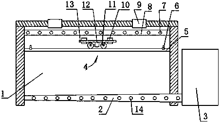
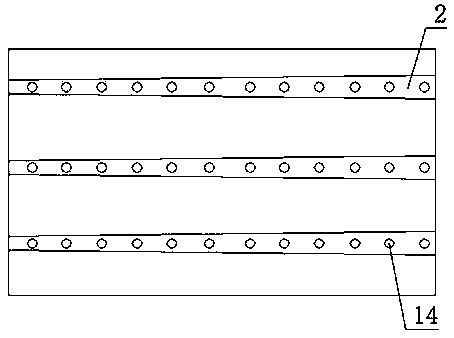
[0023] Such as figure 1 , figure 2 , image 3 As shown, the drying room with a movable air supply system includes a room body 1, and a plurality of air supply drying channels 2 and air outlet pipes 8 are installed in the room body 1, and the air supply drying channels 2 are connected with an air energy heat pump 3 to provide To ensure the hot air needed for baking the room body 1, there are multiple air inlets 14 and air outlets 7 on the outside of the air supply drying channel 2 and the air outlet pipe 8, which can be adjusted according to the size of the room body and the amount of materials to be baked in the room. Determine the opening number of air inlet 14 or air outlet 7. The air-supply drying tunnel 2 is arranged at the bottom of the room body, and the air outlet pipe 8 is arranged at the inside top of the room body. Because the hot air density is relatively small, this design helps the circulation of the hot air in the room. In order to make up for the defect t...

Embodiment 2

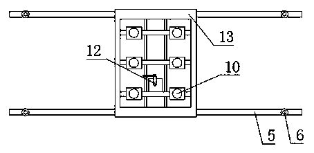
[0027] This embodiment differs from Implementation 1 in that, as Figure 4 , Figure 5 As shown, when the lateral span of the room body 1 of the drying room is relatively large, a lateral air supply system 15 for laterally moving the fan 10 is also provided above the frame 13, and the lateral air supply system 15 includes a small frame 16, a lateral Guide rail 20, transverse guide wheel 18, transverse guide rail 20 is fixed on the frame 13 lateral end edges, blower fan 10, transverse guide wheel 18 are fixed on the small frame 16. The small frame 16 is provided with rotational power by the lateral power system 17. Under the action of the lateral power system 17, the lateral guide wheels 18 run on the top of the horizontal guide rail 20 to drive the small frame 16 to move laterally, and are fixed on the two ends of the lateral guide rail 20. Limit switch 19 controls the travel stroke of small frame 16. Driven by the small frame 16 to move the blower fan 10 laterally back a...


PUM


Abstract

A drying room with a movable air supply system comprises a room body. The movable air supply system is arranged on the upper portion of the inner side of the room body. The movable air supply system is mainly composed of a fan, a rack and a guide rail. The guide rail is fixed to two corresponding side walls of the room body. The rack stretches above the guide rail. Under the action of guide wheels fixed to the two ends of the rack, the rack drives the fan above the rack to move back and forth above the guide rail, and the moving distance of the rack is controlled by limit switches arranged at the two ends of the guide rail. According to the drying room with the movable air supply system, the fan moves transversely or longitudinally in the drying room, so that a ventilation dead angle of materials is avoided, and drying efficiency is improved.

Description

technical field [0001] The invention relates to a drying room, in particular to a drying room with a movable air supply system. Background technique [0002] In the drying room, the flow direction and size of the hot air have an important influence on the drying quality and efficiency of the objects in the room. The existing drying room mainly adopts the method of fixed air inlet and outlet, and the air supply distance of the air supply drying tunnel is generally long, and the air supply pressure gradually decreases with the increase of the air supply distance, so the existing drying room technology is generally Disadvantages such as uneven air volume and material ventilation dead angle seriously affect the drying efficiency. Contents of the invention [0003] The purpose of the present invention is to solve the above-mentioned problems of uneven air volume in the existing drying room and dead ventilation angles for materials. [0004] The present invention realizes abov...

Claims


Application Information

Patent Timeline
Patent Type & Authority Applications(China)
IPC IPC(8): F26B9/02F26B21/00F26B25/00
Inventor 张日安
Owner 盐城江跃机械制造有限公司
Why Eureka
Try Eureka