Indoor position tracking method for pedestrians based on inertial sensors

An inertial sensor and indoor position technology, applied to instruments, measuring devices, and navigation through speed/acceleration measurement, can solve problems such as time-consuming, inconvenient to carry, and poor real-time performance, and achieve position estimation error reduction and improvement The effect of accuracy

Active Publication Date: 2017-04-26
严格集团股份有限公司
View PDF4 Cites 1 Cited by
  • Summary
  • Abstract
  • Description
  • Claims
  • Application Information

AI Technical Summary

Problems solved by technology

Wearable devices were used in the early stage. Sensors were installed on shoes, helmets, pockets, waists, etc. The feet can reflect more movement characteristics during walking, so the foot sensors can better detect steps, but additional Purchase special equipment and it is inconvenient to carry, not suitable for ordinary pedestrian indoor navigation system
During the walking process, the acceleration sensor will output certain walking characteristics. Through peak detection, zero-crossing detection, autocorrelation matching, spectrum analysis, etc. of the measurement data, one or more of them are combined to identify each step. The latter two Real-time performance is not strong due to long time consumption
For step length estimation, the roughest way is to directly set the step length as a constant, because pedestrians have an average step length when walking at a constant speed, but in reality, the step length is affected by a person's height, body shape, step-changing frequency and other factors Influence, cannot be generalized as mean value

Method used


Image

  • Indoor position tracking method for pedestrians based on inertial sensors
  • Indoor position tracking method for pedestrians based on inertial sensors
  • Indoor position tracking method for pedestrians based on inertial sensors

Examples


specific Embodiment approach 1

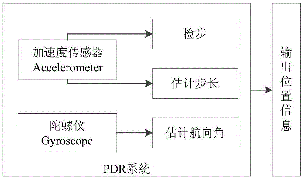
[0021] Specific implementation mode one: the indoor position tracking method for pedestrians based on inertial sensors in this embodiment is implemented in the following steps:

[0022] 1. Step detection and step length estimation based on the acceleration sensor;

[0023] 2. Estimating the heading angle according to the change of the three-axis angular velocity in the gyroscope measurement data, correcting the heading angle, and then performing dead reckoning according to the corrected heading angle and the step length of the first step, and finally according to the step length and heading angle. The PDR method estimates the position:

[0024]

[0025] in, Indicates the estimated position of the PDR at step k h k Represents the heading angle estimated at step k, sLen k Represents the step size of the kth step;

[0026] 3. The map information and PDR estimation results are fused through particle filtering, and the indoor position tracking method of pedestrians based ...

specific Embodiment approach 2

[0027] Embodiment 2: The difference between this embodiment and Embodiment 1 is that the specific process of Step 1 is as follows:

[0028] Use the method of peak value-zero value-valley value-time interval to detect steps, that is, each walking step contains 1 maximum acceleration, 2 zero values, and 1 minimum acceleration, and the time interval is reasonable, and the speed of walking at a normal adult speed is satisfied. 2 to 4 steps per second, set the lower limit of the time interval to 250 milliseconds, S 0 means start, S i , i=1...9 represents the i-th step, and the step size is estimated by the following formula

[0029]

[0030] where sLen is the estimated step size, acc i 、 acc Ave Represent the acceleration value and the average acceleration value in each step, respectively, and N represents the number of data collected in each step.

[0031] Other steps and parameters are the same as those in Embodiment 1.

specific Embodiment approach 3

[0032] Specific embodiment three: the difference between this embodiment and specific embodiment one or two is: the heading angle estimation method in the step two is:

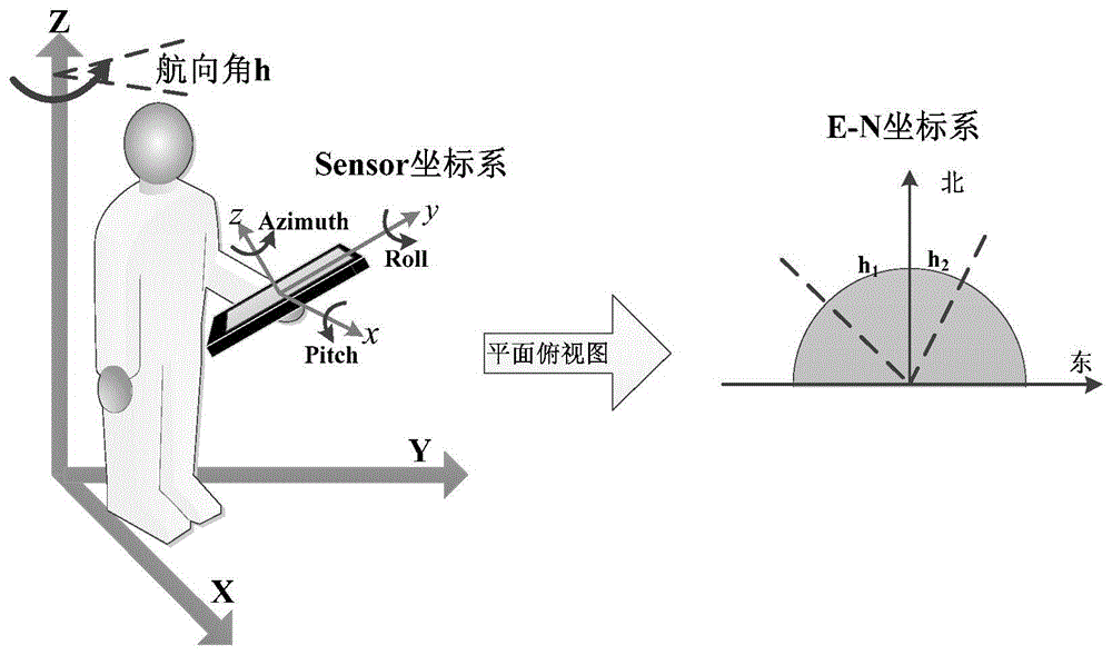
[0033] First, time-integrate the three-axis angular velocity around x, y, and z to obtain the pitch angle, roll angle, and azimuth angle respectively, which are recorded as Pitch, Roll, and Azimuth;

[0034] Use (3) to correct the heading angle in the first step:

[0035] heading=c 1 ·Pitch+c 2 ·Roll+c 3 ·Azimuth (3)

[0036] Among them, the pitch angle Pitch represents the amount of rotation around the x-axis, the roll angle Roll represents the amount of rotation around the y-axis, and the azimuth angle Azimuth represents the amount of rotation around the z-axis, where c 1 ,c 2 ,c 3 is the corresponding weighting coefficient;

[0037] The second step of correction is performed on the heading angle corrected in the first step, that is, successive smoothing, which is specifically calculated by the follow...


PUM


Abstract

The invention discloses a pedestrian indoor position tracking method based on an inertial sensor, relates to a pedestrian indoor position tracking method and particularly relates to a PDR (precision depth recorder) method and a PF fusion map information algorithm based on the inertial sensor. The pedestrian indoor position tracking method disclosed by the invention is used for solving the conditions such as great position estimation errors and even wrong estimation, and the like caused by long-time drift performance of the inertial sensor when only the PDR is used for tracking the pedestrian position. The method comprises the following steps of I. detecting steps and estimating step length according to an acceleration sensor; II. estimating a course angle according to the change of three-axle angular velocity in measured data of a gyroscope, correcting the course angle, carrying out course calculation according to the corrected course angle and the step length of the first step; and finally, estimating the position according to the step length and the course angle through the PDR method; and III. fusing map information with the PDR estimation by particle filtering to complete the pedestrian indoor position tracking method based on the inertial sensor. The pedestrian indoor position tracking method disclosed by the invention is applied to the technical field of indoor positioning.

Description

technical field [0001] The invention relates to a pedestrian indoor position tracking method, in particular to a PDR method based on an inertial sensor and a PF fusion map information algorithm. Background technique [0002] In recent years, the development of Micro-Electro Mechanical Systems (MEMS) has made the application of inertial sensors in smart mobile terminals popular. The pedestrian indoor navigation system based on inertial sensors has gradually become a research hotspot due to its low cost advantage of not needing to lay external facilities. The basic principle of the system is to use pedestrian dead-reckoning (PDR, Pedestrian Dead-Reckoning), according to the measurement data of inertial sensors (such as accelerometers, gyroscopes), mainly involves step detection, estimated step length, estimated heading angle, etc. technology, so this system is sometimes called SHSs (Step-and-Heading Systems). Wearable devices were used in the early stage. Sensors were instal...

Claims


Application Information

Patent Timeline
Patent Type & Authority Patents(China)
IPC IPC(8): G01C21/18
CPCG01C21/16G01C21/206
Inventor 马琳邓仲哲秦丹阳何晨光徐玉滨崔扬
Owner 严格集团股份有限公司
Why Eureka
Try Eureka