

Pedestrian indoor position tracking method based on inertial sensor
An inertial sensor and indoor position technology, applied to instruments, measuring devices, and navigation through speed/acceleration measurement, can solve problems such as time-consuming, inconvenient to carry, and poor real-time performance, and achieve position estimation error reduction and improvement The effect of accuracy
- Summary
- Abstract
- Description
- Claims
- Application Information
AI Technical Summary
Problems solved by technology
Method used
Image

Examples
specific Embodiment approach 1
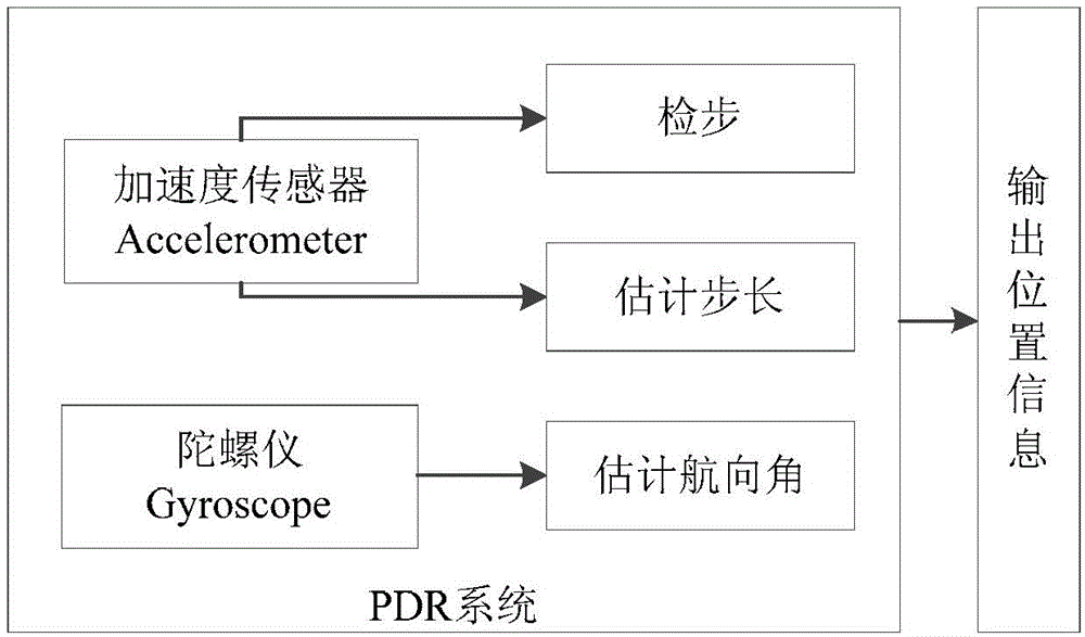
[0019] Specific implementation mode one: the indoor position tracking method for pedestrians based on inertial sensors in this embodiment is implemented in the following steps:
[0020] 1. Step detection and step length estimation based on the acceleration sensor;
[0021] 2. Estimating the heading angle according to the change of the three-axis angular velocity in the gyroscope measurement data, correcting the heading angle, and then performing dead reckoning according to the corrected heading angle and the step length of the first step, and finally according to the step length and heading angle. The PDR method estimates the position:
[0022] pos k PDR = x k y k = ...
specific Embodiment approach 2
[0025] Embodiment 2: The difference between this embodiment and Embodiment 1 is that the specific process of Step 1 is as follows:
[0026] Use the method of peak value-zero value-valley value-time interval to detect steps, that is, each walking step contains 1 maximum acceleration, 2 zero values, and 1 minimum acceleration, and the time interval is reasonable, and the speed of walking at a normal adult speed is satisfied. 2 to 4 steps per second, set the lower limit of the time interval to 250 milliseconds, S 0 means start, S i , i=1...9 represents the i-th step, and the step size is estimated by the following formula
[0027] sLen = 1.07 · acc Ave 3 , acc Ave = Σ i = 1 N ...
specific Embodiment approach 3
[0030] Specific embodiment three: the difference between this embodiment and specific embodiment one or two is: the heading angle estimation method in the step two is:
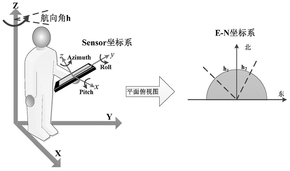
[0031] First, time-integrate the three-axis angular velocity around x, y, and z to obtain the pitch angle, roll angle, and azimuth angle respectively, which are recorded as Pitch, Roll, and Azimuth;
[0032] Use (3) to correct the heading angle in the first step:
[0033] heading=c 1 ·Pitch+c 2 ·Roll+c 3 ·Azimuth
[0034] (3) Among them, the pitch angle Pitch represents the amount of rotation around the x-axis, the roll angle Roll represents the amount of rotation around the y-axis, and the azimuth angle Azimuth represents the amount of rotation around the z-axis, where c 1 ,c 2 ,c 3 is the corresponding weighting coefficient;
[0035] The second step of correction is performed on the heading angle corrected in the first step, that is, successive smoothing, which is specifically calculated by the follow...
PUM
 Abstract
Description
Claims
Application Information