
Two-channel signal transmitting method for LED driving chips

A technology of LED drive and signal transmission, applied in the direction of instruments, static indicators, etc., can solve the problems of unstable symbol period, step-by-step narrowing, and the inability of data signals to effectively represent data information, etc., to achieve infinite cascading, highly reliable effect

Inactive Publication Date: 2014-09-24
苏州卓能微电子技术有限公司
View PDF8 Cites 14 Cited by
  • Summary
  • Abstract
  • Description
  • Claims
  • Application Information

AI Technical Summary

Problems solved by technology

In addition, due to factors such as process inconsistency or changes in the application environment in the process of integrated circuit processing, the pulse width that effectively characterizes the single-line data signal gradually narrows or widens during the transmission process, so that the level When the number of connected chips is large, the data signal transmitted by a single line can no longer effectively represent the data information it carries, resulting in the chip not being able to display color data correctly
This limits the number of single-line data signals transmitted in cascaded LED driver chips, and affects the transmission distance of single-line data signals
Finally, due to factors such as changes in the external environment or unstable power supply, the internal clock of the chip is unstable, or the symbol period of the signal sent by the single-line data signal source is unstable, which will also affect the correct decoding of the single-line data signal by the chip, so that The chip cannot display data correctly

Method used


Image

  • Two-channel signal transmitting method for LED driving chips
  • Two-channel signal transmitting method for LED driving chips
  • Two-channel signal transmitting method for LED driving chips

Examples


Embodiment Construction

[0026] In the following, a further detailed description will be given in conjunction with an example of cascading LED driving chips specifically using the present invention, supplemented by related drawings.

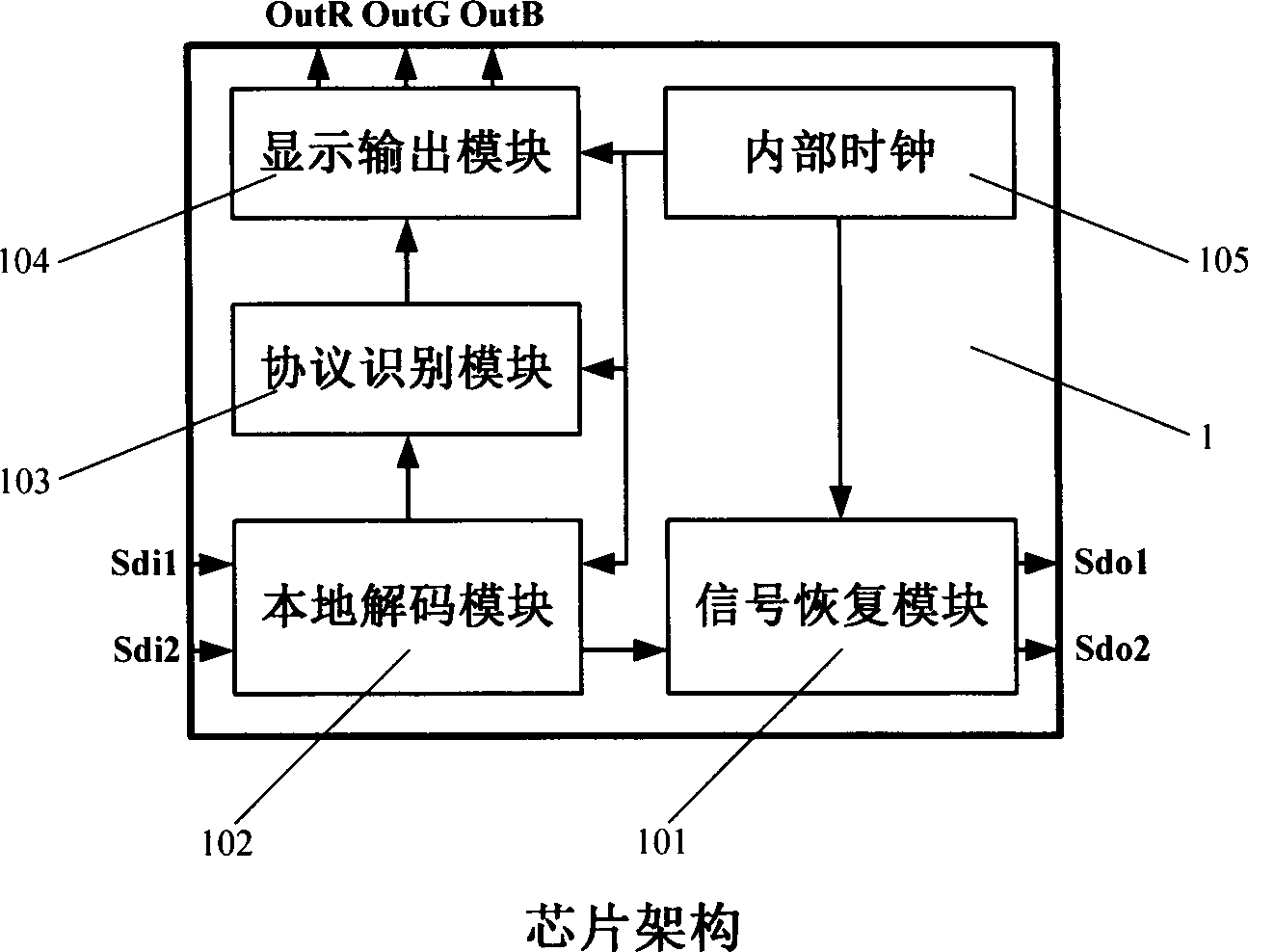
[0027] The chip supports dual-channel single-wire signal transmission with higher transmission priority for input channel 1. In the signal transmission process, each chip generates a synchronous sampling clock according to the received single-wire signal, and then locally decodes the single-wire signal; After the number of bits of the data signal, the chip starts to use the internal clock according to the Manchester code encoding method to quickly and completely restore the single-wire signal and transmit it to the next-level chip; at the same time, the protocol recognition module displays the output module based on the data obtained by local decoding Control to realize the displayed output. Such as figure 1 As shown, the internal architecture of the chip includes a signal ...


PUM


Abstract

The invention discloses a two-channel signal transmitting method for LED driving chips. The method supports two-channel single-line signal transmission with an input channel 1 with the higher transmission priority, in the signal transmitting process, all the chips generate a synchronous sampling clock according to received single-line signals, and then the single-line signals are locally decoded; after a certain bit number of data signals are received, the chips start to utilize internal clocks to fast recover the single-line signals according to the encoding mode of the Manchester code and transmit the single-line signals to the next-level chip; meanwhile, a protocol recognition module controls a display output module according to data obtained through local decoding, and therefore display output can be achieved. The two-channel signal transmitting method can meet high-reliability, high-speed and long-stance single-line signal transmission requirement, and infinite cascading of the LED driving chips can be achieved.

Description

Technical field [0001] The invention relates to a single-wire data signal high-speed transmission protocol and a signal processing method for cascading LED drive chips, and specifically refers to a dual-channel signal transmission method for LED drive chips. Background technique [0002] At present, in the cascaded single-wire data high-speed transmission scheme of LED driver chips, the DALI (Digital Addressable Lighting Interface) protocol or similar transmission protocol is mainly used, and the data is encoded by the return-to-zero code, and the high-speed data is realized through a signal line. transmission. In the actual application process, the aging of the transmission interface due to poor welding or excessive use time will cause the transmission line to fall off, resulting in unreliable transmission. In the case of showing the audience beautiful lighting effects in important festivals, these unreliability is not allowed. In addition, due to the inconsistency of the proc...

Claims


Application Information

Patent Timeline
IPC IPC(8): G09G3/32
Inventor 程玉华
Owner 苏州卓能微电子技术有限公司
Learn More