Self-locking safe power supply socket

A safe power supply, self-locking technology, applied in circuits, electrical components, coupling devices, etc., can solve problems such as deterioration, far-fetched structure, and hidden safety hazards, and achieve the effects of convenient operation, wide application and high safety.

Active Publication Date: 2014-09-24
临沂高新资源开发建设集团有限公司
View PDF5 Cites 10 Cited by
  • Summary
  • Abstract
  • Description
  • Claims
  • Application Information

AI Technical Summary

Problems solved by technology

[0002] The traditional power socket relies on the rigidity of the guide reed to clamp the power plug. Due to the high rigidity, it will be difficult to insert and pull out the plug, so it is easy to loosen and lose power during use within the limited rigidity range. Mobile power boards commonly used in construction sites or other temporary occasions
Open sockets, on the other hand, are an inherent defect of conventional power sockets, and even if devices with sliding protective doors are available, it is very inconvenient to insert the plug, and it is almost impossible to prevent, for example, children from inserting metal objects into it. electric shock hazard
Although some kind of safe power socket that can tighten the plug and (or) can cut off the power supply to prevent electric shock when not in use has appeared in recent years, it is far from the clamping function and deteriorates the structure, which is far from meeting the requirements of the national standard. The requirement that the distance between different conductors is more than 3mm will cause serious safety hazards
The identification mechanism of this type of socket for the shape of the plug is too simple, so that when a child inserts a tweezers-type metal object into the socket, there is still a high probability of starting the socket to be electrified

Method used


Image

  • Self-locking safe power supply socket
  • Self-locking safe power supply socket
  • Self-locking safe power supply socket

Examples


Embodiment Construction

[0028] The following will clearly and completely describe the technical solutions in the embodiments of the present invention. Obviously, the described embodiments are only some of the embodiments of the present invention, rather than all the embodiments. Based on the embodiments of the present invention, all other embodiments obtained by persons of ordinary skill in the art without making creative efforts belong to the protection scope of the present invention.

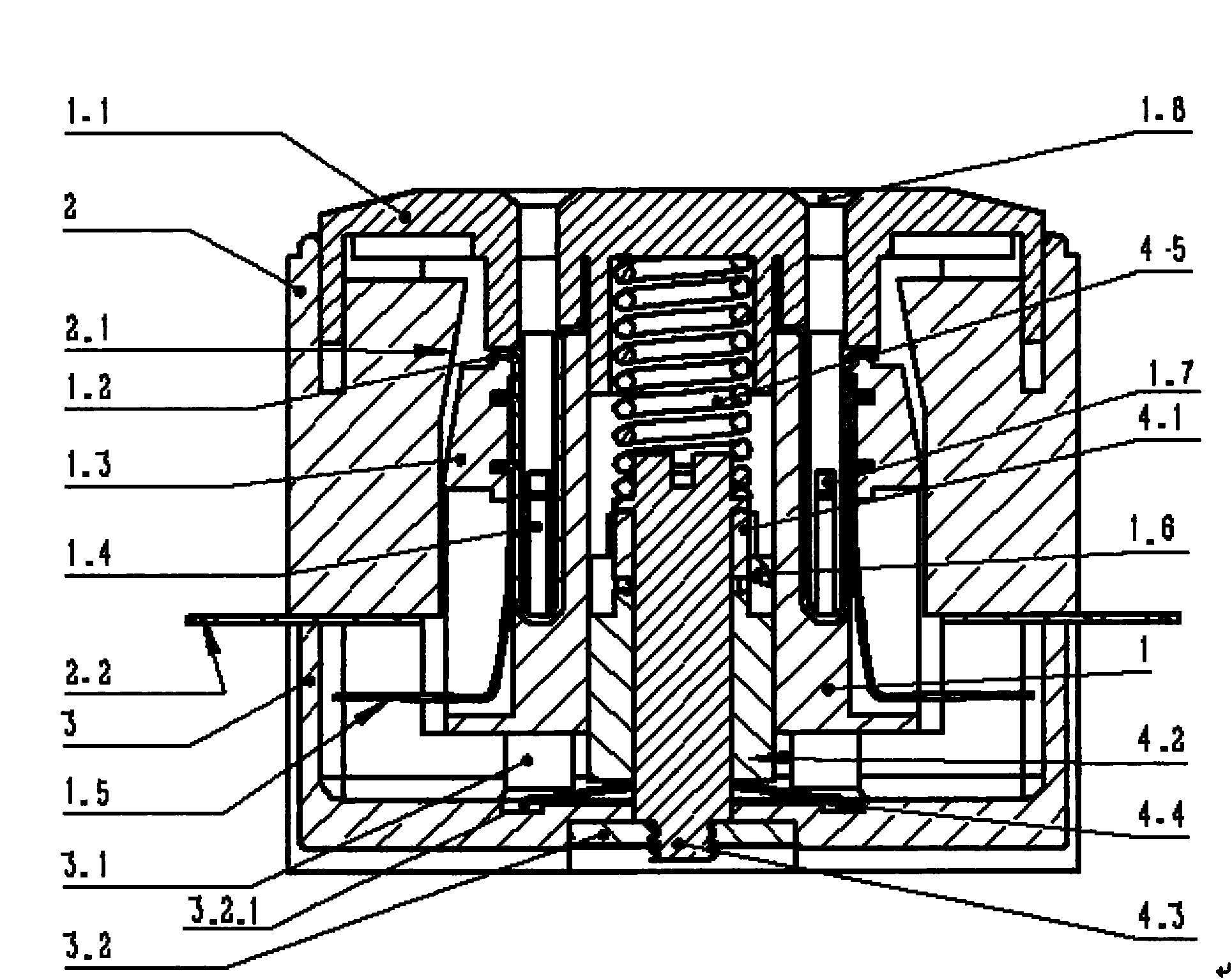
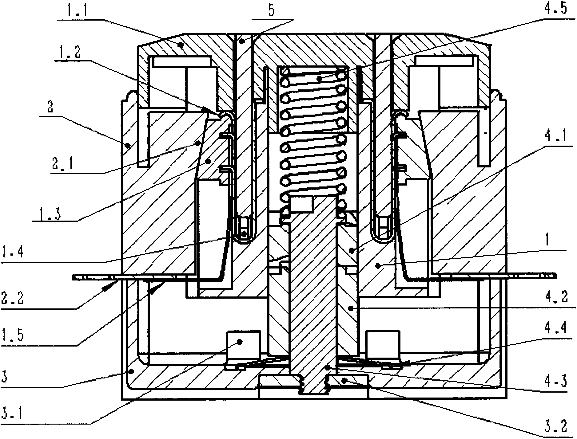
[0029] see figure 1The self-locking safety power socket shown includes a fixed frame 3.2 and a lower casing 3 whose bottom end is embedded in the fixed frame 3.2 through a groove, and a central shaft whose bottom end passes through the lower casing 3 and is fixedly connected to the fixed frame 3.2 4.3. The upper casing 2 arranged on the upper end surface of the lower casing 3, and the compression spring 4.5 arranged on the top of the central axis 4.3, the longitudinal section of the fixing frame 3.2 is U-shaped, and ...


PUM


Abstract

The present invention discloses a self-locking safe power supply socket. The self-locking safe power supply socket is mainly composed of a core body, a compressed spring, a rotary ratchet self-locking mechanism, an upper shell and a lower shell. The core body possesses a plug hole, a current carrying reed, a self lubricating wedge block, a moving contact and a stroke limiting rod. The compressed spring is arranged at the axis part of the core body, and the core body can do up and down limited movement along the axis. The rotary ratchet self-locking mechanism is composed of a rotating ratchet, a fixing ratchet, a central shaft and an inner circular ratchet of the core body. Under the action of continuously pressing a plug after the plug is inserted or under the elastic force of the compressed spring, a use state that the core body is unlocked to be released upwards or a standby state that the core body is locked slightly downwards is realized, so that the self-locking safe power supply socket of the present invention has the functions of preventing the plug from disengaging because of uncertain external forces at use, preventing electric shock caused by that a metal article is inserted in the plug accidently, and preventing the power supply short circuit faults, and is high in safety.

Description

technical field [0001] The invention relates to a reliable and safe mains power output device, in particular to a self-locking safety power socket applied to all power connection occasions (explosion-proof) that emphasize reliable connection and ensure safety. Background technique [0002] The traditional power socket relies on the rigidity of the guide reed to clamp the power plug. Due to the high rigidity, it will be difficult to insert and pull out the plug, so it is easy to loosen and lose power during use within the limited rigidity range. Common mobile power panels used in construction sites or other temporary occasions. Open sockets, on the other hand, are an inherent defect of conventional power sockets, and even if devices with sliding protective doors are available, it is very inconvenient to insert the plug, and it is almost impossible to prevent, for example, children from inserting metal objects into it. Electric shock hazard. Although some kind of safe power ...

Claims


Application Information

Patent Timeline
Patent Type & Authority Applications(China)
IPC IPC(8): H01R13/713H01R13/639
Inventor 张行钢
Owner 临沂高新资源开发建设集团有限公司
Why Eureka
Try Eureka