Method for assisting a traffic light phase assistant of a vehicle, which detects a traffic light

A technology of traffic lights and auxiliary devices, applied in the direction of control devices, vehicle components, automatic starting devices, etc.

Active Publication Date: 2014-09-24
CONTI TEMIC MICROELECTRONIC GMBH +1
View PDF4 Cites 12 Cited by
  • Summary
  • Abstract
  • Description
  • Claims
  • Application Information

AI Technical Summary

Problems solved by technology

[0003] However, the prerequisite for this is that the tra

Method used


Image

  • Method for assisting a traffic light phase assistant of a vehicle, which detects a traffic light
  • Method for assisting a traffic light phase assistant of a vehicle, which detects a traffic light

Examples


Embodiment Construction

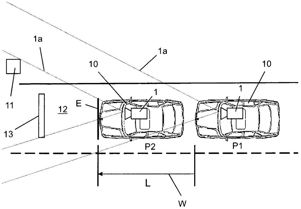
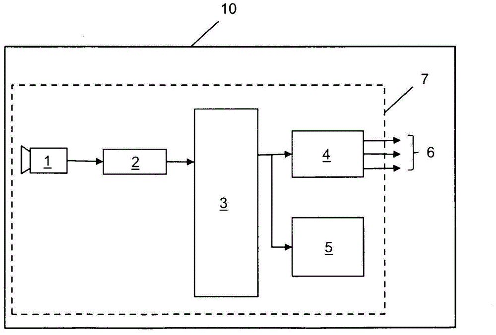
[0021] figure 1 The situation is shown in front of a traffic light 11 towards which a vehicle traveling on a roadway 12 , for example a motor vehicle 10 with a traffic light phase assist system 7 , is approaching. The traffic light phase assistance system 7 has a camera 1 in the form of a stereo camera or a monocular camera with a viewing range 1 a from which the image data of the camera are obtained according to figure 2 sent to the image analysis unit 2. With the aid of object recognition software such as figure 1 traffic lights 11.

[0022] according to figure 1 , vehicle 10 is approaching traffic light 11 and is here initially in position P1 . In this position P1, the traffic light 11 is recognized by the camera 11, and the geographical position of the traffic light 11 and its distance to the vehicle 10 are determined or estimated from the image data, and said data are supplied to the control unit 3 (cf. figure 2 ). When a red light phase is detected, vehicle 10 mu...


PUM


Abstract

The invention relates to a method for assisting a traffic light phase assistant of a vehicle (10), which detects the traffic light phases of a traffic light (11) by means of a camera (1). According to the invention there is provision that when a traffic light (11) is detected in the field of vision (1a) of the camera (1) the length (L) of the travel path (W) in the direction of the traffic light (11) which keeps the camera (11) in its field of vision (1a) is determined by means of a control unit (3), and a control signal (St) which relates to the length (L) of the travel path (W) is output.

Description

technical field [0001] The invention relates to a method for assisting a traffic light phase assistant of a vehicle, which detects a traffic light phase of a traffic light by means of a camera. Background technique [0002] DE 10 2010 052 964 A1 discloses a driver assistance device having a camera for detecting the red phase of a traffic light system. When such an object is detected, the vehicle is regeneratively braked depending on the identified traffic light phase until the vehicle comes to a stop next to the stop line in front of the traffic light. [0003] A prerequisite for this, however, is that the traffic light must remain in the visible range of the camera. This also applies in particular to auxiliary functions which are active from a standstill, such as automatically starting the drive motor of the vehicle when changing from a red to a green phase of a traffic light, for example. Contents of the invention [0004] Starting from this prior art, the object of th...

Claims


Application Information

Patent Timeline
IPC IPC(8): B60W30/18B60W40/04B60W50/14B60W10/18B60W10/184
CPCB60W30/18109B60T7/12G06K9/00825B60W10/18B60W2550/22B60W2420/42B60W40/04B60T7/18B60W10/184B60W50/14B60W30/18154B60W30/181B60W30/00B60W2555/60G06V20/584
Inventor S·吕克S·黑格曼M·科马尔
Owner CONTI TEMIC MICROELECTRONIC GMBH
Why Eureka
Try Eureka