Milling machine fixture

A milling machine fixture and bottom plate technology, applied in the direction of clamping, manufacturing tools, supports, etc., can solve the problems of processing accidents, low processing quality, affecting quality, etc., and achieve the effects of high positioning accuracy, simple and compact structure, and accurate and reliable installation.

Inactive Publication Date: 2014-10-01
SUZHOU CHUANGFENG PRECISION HARDWARE
View PDF7 Cites 1 Cited by
  • Summary
  • Abstract
  • Description
  • Claims
  • Application Information

AI Technical Summary

Problems solved by technology

[0003] However, the current fixtures have the following problems in the actual machining process of the machine tool: the clamping force of the fixture is not suitable, some clamping force is too small, the workpiece moves during the processing and the fixture positioning fails, which not only affects the quality, but also can cause Processing accidents; the clamping force of some fixtures is too large, which will not only deform the workpiece and the fixture itself, but also the processing quality is not high

Method used


Image

  • Milling machine fixture

Examples


Embodiment Construction

[0019] In order to enable those skilled in the art to better understand the solution of the present invention, and to make the above-mentioned purpose, features and advantages of the present invention more obvious and understandable, the present invention will be further described in detail below in conjunction with the embodiments and the accompanying drawings of the embodiments.

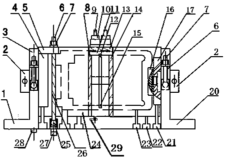
[0020] Such as figure 1 As shown, the present invention provides a milling machine fixture, which mainly includes a bottom plate 24, a first V-shaped block 1, a second V-shaped block 20, at least one set of screw sets, an upper sliding block 12 and a lower sliding block 15, the above-mentioned first A V-shaped block 1 and a second V-shaped block 20 are respectively arranged on the left and right sides of the above-mentioned bottom plate 24, and the above-mentioned first V-shaped block 1 and the second V-shaped block 20 are L-shaped iron blocks whose end faces are provided with V-shaped grooves The ...


PUM


Abstract

The invention discloses a milling machine fixture. The milling machine fixture comprises a bottom plate, a first V-shaped block, a second V-shaped block, at least one screw rod group, an upper sliding block and a lower sliding block, the first V-shaped block is arranged at the left side of the bottom plate while the second V-shaped block is arranged at the right side of the bottom plate, both the first V-shaped block and the second V-shaped block are L-shaped iron blocks, and a V-shaped slot is formed in the head face of each of the first V-shaped block and the second V-shaped block; the screw rod group is fixed on the bottom plate and comprises two screw rods engaged to each other through gears, both the upper sliding block and the lower sliding block are arranged on the screw rods, and the screw rods pass through the upper sliding block and the lower sliding block; a rotating handle is arranged at the lower end of one screw rod to drive the screw rod to rotate. The milling machine fixture has high locating precision, the clamping force of the fixture is proper, and moreover, the fixture has enough rigidity and stability so that the regulation is facilitated.

Description

technical field [0001] The invention relates to a clamp device, more specifically, to a movable clamping force adjustable clamp for a milling machine. Background technique [0002] In the technology of machining parts with machine tools, it is generally necessary to fix the parts that need to be processed by fixtures. First of all, it is necessary to determine the relative position of the workpiece and the tool on the machine tool, and then the fixture exerts force on the workpiece to clamp the workpiece. The whole process from workpiece positioning to workpiece clamping is clamping. The main function of the milling machine fixture is to complete the clamping and fixing of the workpiece, and the quality of the clamping of the workpiece directly affects the machining accuracy of the workpiece. [0003] However, the current fixtures have the following problems in the actual machining process of the machine tool: the clamping force of the fixture is not suitable, some clamping...

Claims


Application Information

Patent Timeline
IPC IPC(8): B23Q3/06
CPCB23Q3/06
Inventor 徐德明
Owner SUZHOU CHUANGFENG PRECISION HARDWARE
Why Eureka
Try Eureka