Automatic feeding and discharging machine of petroleum pipe threading lathe

A technology of automatic loading and unloading, thread lathe, used in metal processing equipment, tangent devices, manufacturing tools, etc., can solve the problems of thread processing quality and supply of drill pipe and collars, high labor intensity, poor sealing and other problems , to achieve the effect of ensuring exploration, development and production and avoiding stuck drilling and buried drilling

Pending Publication Date: 2021-06-01
肖硕
View PDF1 Cites 1 Cited by
  • Summary
  • Abstract
  • Description
  • Claims
  • Application Information

AI Technical Summary

Problems solved by technology

[0013] 4.2. Pushing the trolley to manually feed the machine tool, it is difficult to penetrate the spindle hole at one time, resulting in frequent impacts on the rear chuck. At that time, there were 5 pipe beds in the pipe thread processing workshop in the oil field. Every year, each machine tool was shut down for maintenance for one week to replace the chuck. It costs 20,000 to 30,000 yuan. Due to the frequent impact of the spindle bearing, the precision drops rapidly. It is difficult to guarantee the quality of thread processing and the quantity of drill pipes and collars supplied.
[0015] 4.4. It has been proved that the original trolley loading and unloading processing thread crane is too busy, the thread processing efficiency is low, the labor intensity is high, the safety factor is low, the support center line of the pipe and the machine tool center line are difficult to coincide, and the hole is not allowed to collide and affect The service life of the machine tool, the surface of the processed thread has ripples, the seal end face has a large runout, the surface roughness does not meet the requirements, and the pipe is not well sealed when the thread is used to connect. Due to the development of the oil field and the gradual growth of the oil field, the supply of drilling tools for the well team is often in an emergency. Drill collar thread reaches the repair state and cannot be repaired. Tripping accidents often occur or the sealing surface is not sealed when it is used continuously. Type failure, the liquid flow does not flow out through the drill bit and is short-circuited, the liquid flow and pressure at the drill bit decrease or the liquid flow stops circulation, and the broken rock cutting is not smooth, causing the rock cutting to sink and stick the drill or bury the drill string. If it happens, the whole well will even be scrapped, resulting in huge losses. The old-fashioned feeding and unloading method of the pipe thread machine tool is inefficient. The well crew is often in a hurry waiting for the drilling tool to spud out. The thread processing lathes for drilling tools in the oil field are going to be increased from 5 to 10. If the loading and unloading method is not changed, the thread processing efficiency will not be improved if the loading and unloading method is not changed. Due to backwardness, it is urgent to study a new loading and unloading machine that reduces the utilization rate of cranes, has high thread processing efficiency, good thread quality, improves safety factor and reduces labor intensity of personnel.
However, since the feeding and feeding process of this structure is controlled by the flap inlet and outlet device, the flap inlet and outlet device will be hit frequently, the accuracy will drop rapidly, and the thread processing quality is difficult to guarantee. In addition, the righting of the structure The device has the function of adjusting the position of the pipe. However, since the length of the processed pipe is about 9.5 meters, each pipe has the problem of non-straightness and deflection. It is still impossible to solve the problem of the center of the pipe and the center of the machine tool spindle only by the bottom support without clamping. Deviation, vibration when the machine tool rotates, the impact on the accuracy of the machine tool and the quality of the processed pipe thread, and the problem of often hitting the rear chuck

Method used


Image

  • Automatic feeding and discharging machine of petroleum pipe threading lathe
  • Automatic feeding and discharging machine of petroleum pipe threading lathe
  • Automatic feeding and discharging machine of petroleum pipe threading lathe

Examples


Embodiment 1

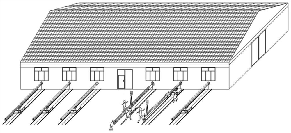
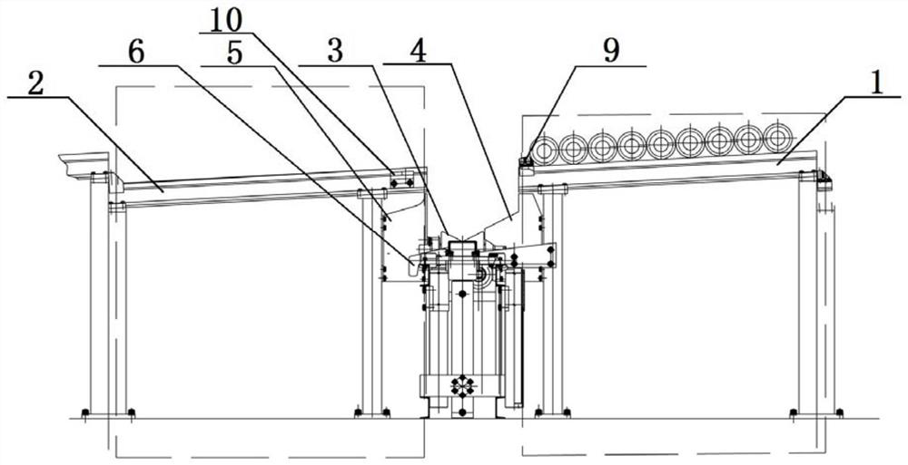
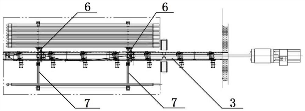
[0073] refer to Figure 2-34 , the automatic loading and unloading machine for oil pipe thread lathe provided by the present invention comprises: loading table area 1, unloading table area 2, roller conveying mechanism 3 between loading table area 1 and unloading table area 2, connecting feeding The feeding deflector 4 of the table area 1 and the roller conveying mechanism 3, the unloading deflector 5 connecting the unloading table area 2 and the roller conveying mechanism 3, installed between the feeding table area 1 and the unloading table area 2 A group of a total of two loading and unloading conveying mechanisms 6; wherein the loading platform area 1 and the unloading platform area 2 are composed of a set of heavy rails 7 and a column 8 supported under the heavy rails 7. Support with inclined surfaces frame, the end of the loading platform area 1 close to the roller conveying mechanism 3 is lower and the end is provided with an adjustment block 9, and the adjustment block ...

Embodiment 2

[0081] In this embodiment, utilizing the rolling characteristics of cylindrical pipes, a loading table area 1 and a feeding table area 2 with an inclined surface are designed to make the pipes roll automatically and orderly on the surface, and the loading and unloading process of the roller conveying mechanism 3 is also used The characteristics of the cylindrical pipe rolling on the inclined surface, on the basis that the pipes on the inclined surfaces of the feeding table area 1 and the unloading table area 2 have automatic rolling to generate displacement, pass through the feeding inclined surface and unloading inclined surface of the upper and lower material plate 601, and the conveying roller The V-shaped slope of 304 completes a series of dynamic position changes of the pipe, forming an automatic loading and unloading block for the pipe.

[0082] In this embodiment, during the loading and unloading process, the pipe material rolls along the inclined surface of the loading ...


PUM


Abstract

The invention provides an automatic feeding and discharging machine for a petroleum pipe threading lathe. The automatic feeding and discharging machine comprises a feeding table area, a discharging table area, a roller conveying mechanism located between the feeding table area and the discharging table area, a feeding guide plate connected with the feeding table area, the discharging table area and the roller conveying mechanism, a discharging guide plate connected with the discharging table area and the roller conveying mechanism and a feeding and discharging conveying mechanism, wherein the end, close to the roller conveying mechanism, of the feeding table area is low and provided with an adjusting check block, the end, close to the roller conveying mechanism, of the discharging table area is high and provided with an anti-impact check block, and the roller conveying mechanism is used for conveying pipes to a machining area of the pipe threading lathe; the roller conveying mechanism comprises a rack, a conveying roller mechanism and a conveying roller lifting adjusting mechanism; and the feeding and discharging conveying mechanism comprises a feeding and discharging plate, an oil cylinder, a guide sleeve and a guide centralizing rod. The automatic feeding and discharging machine has the advantages that batch automatic feeding and discharging operation of pipes with male threads and female threads of various drill rods, drill collars, casing pipes and oil pipes can be achieved, and production efficiency is improved.

Description

technical field [0001] The invention belongs to the technical field of oil pipe thread processing, and more specifically relates to an automatic loading and unloading machine for an oil pipe thread lathe. Background technique [0002] Drill pipes, drill collars, casings, and oil pipes in the field of oil and energy are important special pipes for oil field development and production. They are generally lowered into wells below the ground. Each pipe is threaded one by one by the male and female threads at both ends. In particular, drill pipes and drill collars are necessary tools for drilling. During the drilling process, they are often pulled out and tripped one by one or three by one. The connected threads need to be re-drilled in two or three wells. New machining or repair of threads on pipe thread lathes. [0003] The pipe thread lathe is a special machine for processing various oil pipe threads, and the pipe loading and unloading machine is a special machine specially d...

Claims


Application Information

Patent Timeline
Patent Type & Authority Applications(China)
IPC IPC(8): B23G11/00
CPCB23G11/00
Inventor 肖树槐肖硕肖思源
Owner 肖硕
Why Eureka
Try Eureka