
Fully automatic single punching manipulator

A robotic and fully automatic technology, applied in metal processing and other directions, can solve the problems of high labor intensity, high labor intensity, and high risk of work-related injuries, and achieve the effect of improving the production rate, saving labor, and reducing labor intensity.

Active Publication Date: 2015-12-09
SHENZHEN MAKEN M & E
View PDF8 Cites 0 Cited by
  • Summary
  • Abstract
  • Description
  • Claims
  • Application Information

AI Technical Summary

Problems solved by technology

However, there are problems such as high labor intensity, high risk of work-related injuries, high labor intensity, unstable personnel, etc.
[0004] However, corresponding to the blanking process, in addition to the continuous processing, there is also a single processing method. The main difference between the two is that the continuous processing method is to directly discharge the waste. After the sequential processing is completed, only the entire product is left. , just take it away; and the processing method of a single piece is that a single product is generated for each punching, and the next punching is performed after the punching is taken away. After the punching is completed in sequence, the entire waste is left and finally taken away; Therefore, the operation process is more complicated
The original automatic punching manipulator is not suitable for single-piece processing. In the existing technology, only manual production can be used to deal with single-piece production. The problem of not being able to improve this efficiency has always plagued manufacturers.

Method used


Image

  • Fully automatic single punching manipulator
  • Fully automatic single punching manipulator
  • Fully automatic single punching manipulator

Examples


Embodiment 1

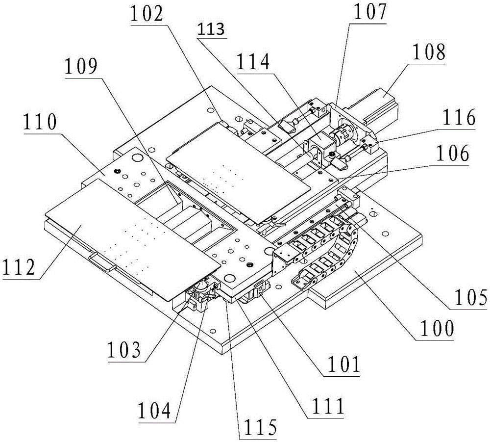
[0065] Further, such as image 3 In the punching device shown above:

[0066] The second substrate mechanism includes a second bottom plate 100, a sensor shield 102, a tray lifting rod 103, a tray seat 104, a funnel 109 and a cleaning air blowing seat 116;

[0067] The Y-axis translation mechanism includes a cylinder 101, a linear slide rail 105, a mold support block 106, a servo motor mounting plate 107, a servo motor 108, a ball screw 113, and a ball screw mounting seat 114;

[0068] The mold installation mechanism includes a mold installation plate 110 , a moving plate 111 and a guide post / guide sleeve 115 .

[0069] A linear slide rail 105 is installed on the second bottom plate 100, and a moving plate 111 is slidably connected to the linear slide rail 105. A mold mounting plate 110 is arranged on the moving plate 111, a funnel 109 is installed on the mold mounting plate 110, and a tray panel 112 is arranged above the funnel 109. .

Embodiment 2

[0071] Further, such as Figure 4 , 5 As shown, the above-mentioned horizontal transport device includes a transporter plate 201, a stepper motor 202, a synchronous wheel 203, a synchronous belt 204, a stepper motor mounting plate 205, a synchronous wheel seat 206, a synchronous wheel 207, a synchronous belt 208, and a linear slide rail 209 , Slide rail pad 210, idler seat 211, timing belt tensioning mechanism 212, limit block 213, timing belt fixing block 214, tank chain 215.

[0072] The two ends of one side surface of the conveyor plate 201 are respectively provided with a stepper motor 202 through a stepper motor mounting plate 205, the output shaft of the stepper motor 202 is connected with a synchronous wheel 203, and the synchronous wheel 203 is sleeved on the synchronous belt 204, and the synchronous belt 204 connects the two stepper motors 202 through the synchronous wheel 207 arranged on the synchronous wheel seat 206 on the other side of the conveyor plate 201 . T...

Embodiment 3

[0074] Further, such as Figure 6 , 7 In the above-mentioned feeding tray device as shown:

[0075]The X-axis translation mechanism includes the workpiece position adjustment knob 302 , the workpiece position fixing block 303 , the position fixing handle 304 , the position adjustment wire motherboard 305 , the position adjustment bearing seat 306 and the product position sensor 307 .

[0076] The lifting plate mechanism includes a third base plate 301, a lifting base plate 308 of workpieces to be processed, a lifting plate 309, a lifting frame panel 310, a tray base plate 311, a tray panel 312, a lift guide shaft 317, a lift guide bearing 318, and a tray panel support column 319 , positioning the central axis of rotation 320 of the needle.

[0077] The workpiece adjustment mechanism includes a product position sensor 307 , a positioning pin 313 of the workpiece to be processed, a positioning pin mounting bar 314 , a linear slide rail 315 and a position adjustment rotating me...


PUM


Abstract

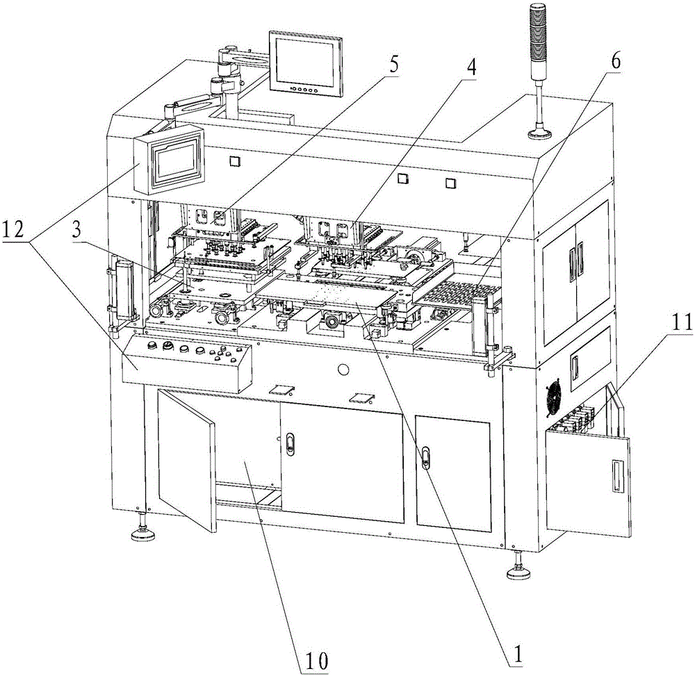
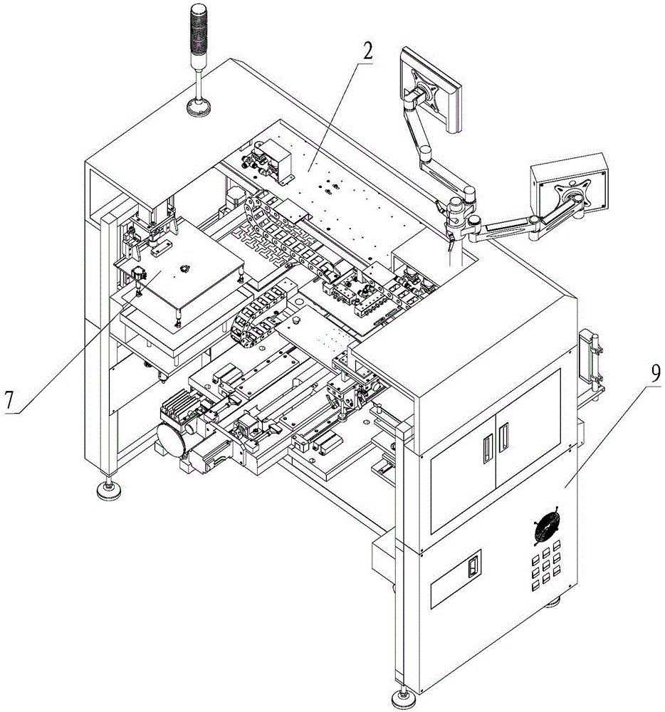
The invention provides a fully-automatic single blanking mechanical arm. A loading plate device, a loading arm device, a blanking device, a horizontal conveying device, an unloading arm device, an upper partition paper device and a finish product collecting device are mounted on an existing punch press to form an excellent structural design, so that the fully-automatic single blanking mechanical arm can complete operations of loading, conveying, blanking, movement and the like of FPC (flexible printed circuit) boards; the cooperation of all the parts enables the fully-automatic single blanking mechanical arm to meet the requirements of single production, so that the problems existing in the signal production such as high labor intensity, high work-related injury risk, low production efficiency, large worker quantity and personnel instability can be solved.

Description

technical field [0001] The invention relates to a printed circuit board production equipment, in particular to a fully automatic single punching manipulator. Background technique [0002] At present, in the circuit board industry, especially the flexible circuit board (also known as FPC), there is a process of punching the shape of the circuit board, which is also called punching in the industry. The method generally adopted in the existing industry is that one person operates a punching machine, and the shape of the circuit board is processed at one time by die-cutting. This method has the advantages of high production efficiency, low cost, and good consistency. However, there are problems such as high labor intensity, high risk of work-related injuries, high labor intensity, and unstable personnel. [0003] With the development of the economy, the rising cost of labor and the sharp decline of skilled workers, the traditional production method relying on manual operation ...

Claims


Application Information

Patent Timeline
Patent Type & Authority Patents(China)
IPC IPC(8): B26F1/38B26D7/06B26D7/32
Inventor 史洪智
Owner SHENZHEN MAKEN M & E
Learn More