Efficient engraving and milling machine

An engraving and milling machine and high-efficiency technology, applied in the mechanical field, can solve problems such as decreased work efficiency and impact on engraving accuracy, and achieve the effects of ensuring quality, improving production efficiency, and ensuring accuracy

Active Publication Date: 2014-10-01
陈美青
View PDF11 Cites 23 Cited by
  • Summary
  • Abstract
  • Description
  • Claims
  • Application Information

AI Technical Summary

Problems solved by technology

When the engraving and milling machine is engraving, because the workpiece is placed horizontally, the debris generated during engraving will stay on the workpiece, which will affect the accuracy of the engraving; after a long period of engraving, a large amount of debris will accumulate on the workbe

Method used


Image

  • Efficient engraving and milling machine
  • Efficient engraving and milling machine
  • Efficient engraving and milling machine

Examples


Embodiment 1

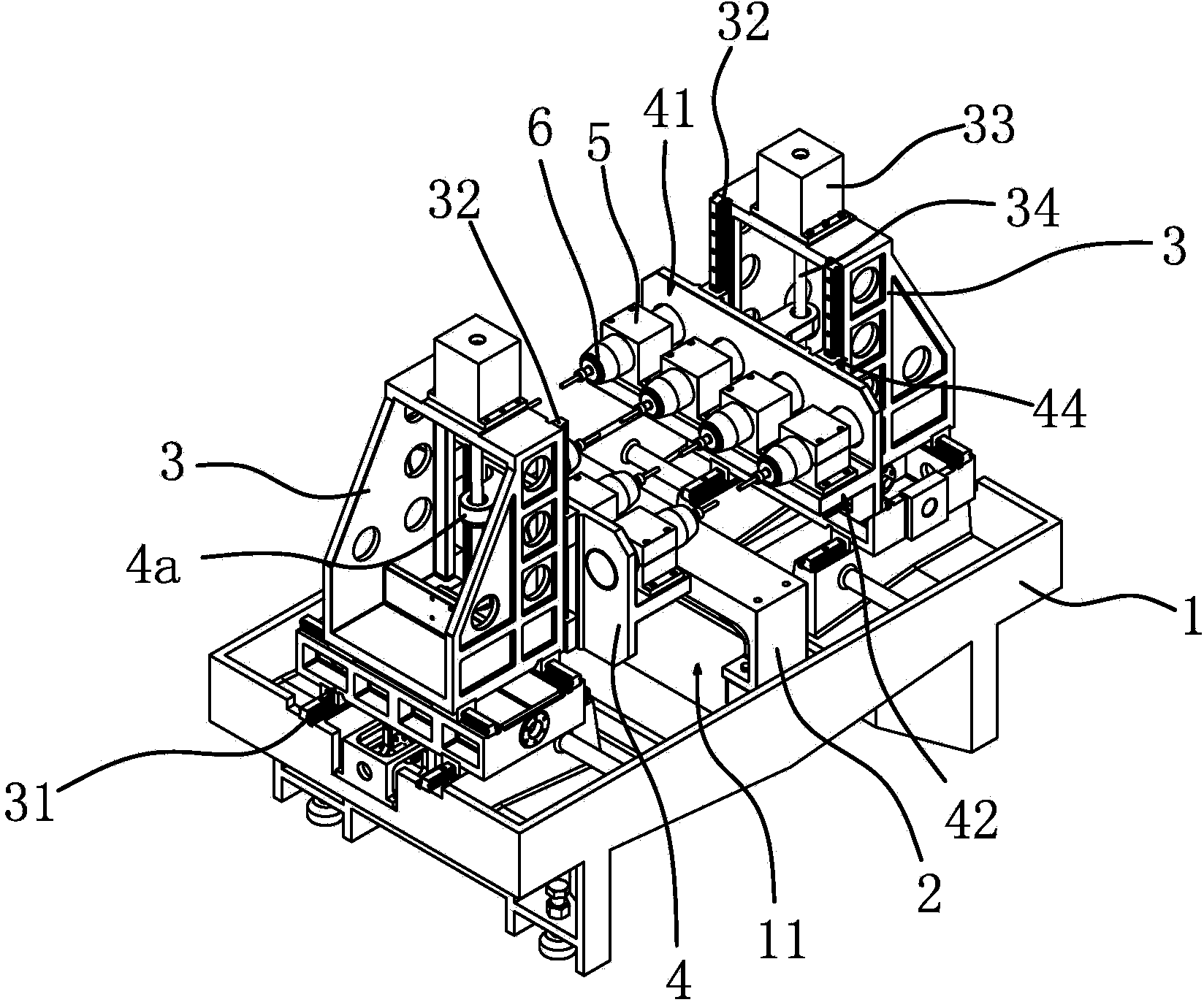
[0028] Such as figure 1 As shown, a high-efficiency engraving and milling machine includes a workbench 1, and the middle part of the workbench 1 is fixed with a fixed table 2 for fixing workpiece fixtures. The fixed table 2 is elongated, and several workpiece fixtures can be fixed on the fixed table 2. The processed workpiece is fixed on the fixed table 2 by the workpiece fixture. The workbench 1 is located below the fixed table 2 and has a recovery hole 11 for collecting debris. The recovery hole 11 is elongated; the width of the upper end port of the recovery hole 11 is greater than The width of the workbench, the fixed platform 2 is located directly above the middle part of the upper port of the recovery hole, the cross section of the fixed platform 2 is trapezoidal, and both sides of the fixed platform 2 have inclined surfaces 21, and debris slides to the recovery hole 11 through the guidance of the inclined surfaces 21, Prevent accumulation on the fixed table 2.

[0029]...

Embodiment 2

[0035] The structure and principle of this embodiment are basically the same as that of Embodiment 1. The difference lies in that the mounting plate and the bracket are connected by cross guide rails, and guide rails are fixed on the workbench. The table is vertical, the bracket is slidably connected to the guide rail, and the drive source capable of driving the bracket to slide along the guide rail is fixed on the workbench. The driving source can be a motor or a cylinder. The bracket can drive the engraving and milling motor away from or close to the worktable. The driving source drives the engraving and milling motor to move freely on a plane perpendicular to its output shaft, realizing the movement of the engraving and milling motor along three degrees of freedom.

Embodiment 3

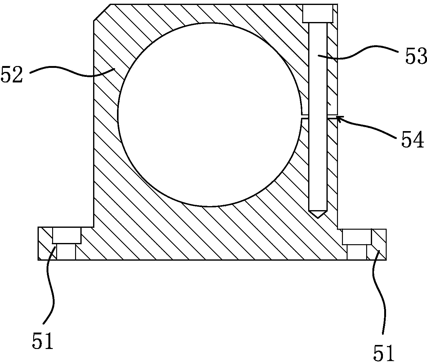
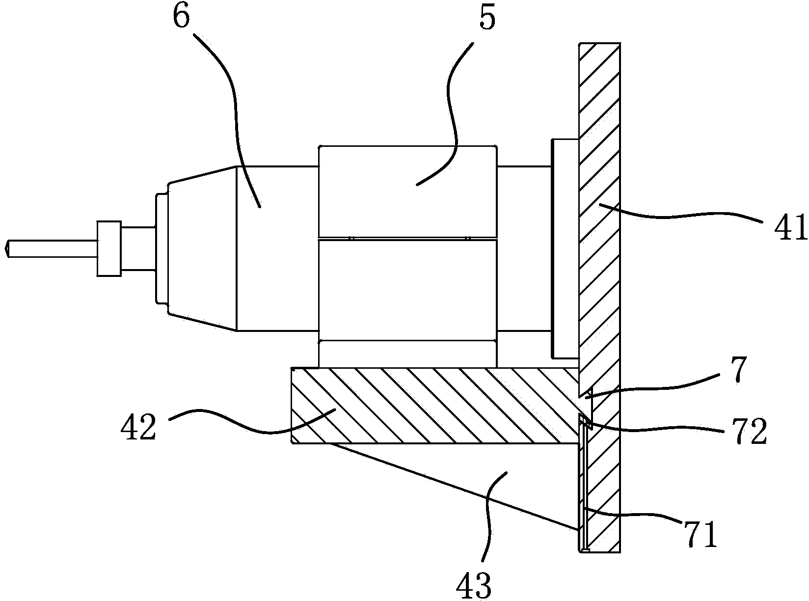
[0037] The structure and principle of this embodiment are basically the same as that of Embodiment 1, the difference is that: image 3 As shown, the mounting plate 4 includes a strip-shaped fixed plate 41 and several support plates 42, the fixed plate 41 is connected to the support 3, the fixed plate 41 is parallel to the table top of the workbench 1, and the fixed plate 41 is provided with an engraving and milling motor 6 There are positioning grooves distributed along the length direction of the fixing plate 41 on the side of the positioning groove, the width of the notch of the positioning groove is smaller than the width of the bottom surface of the positioning groove, the support plate 42 is arranged horizontally, and the support plates 42 are distributed sequentially along the length direction of the fixing plate 41, each The upper plate surface of the support plate 42 is fixed with the shaft center fixing seat 5, the engraving and milling motor 6 is positioned on the sup...


PUM


Abstract

The invention provides an efficient engraving and milling machine and belongs to the field of mechanical technology. The efficient engraving and milling machine solves the problem that scraps generated during the engraving process of existing engraving and milling machines can stay on workpieces to result in influence on the engraving efficiency and the like. The efficient engraving and milling machine comprises a working table, a support and a plurality of engraving and milling motors, wherein the working table is provided with a fixing table for fixing workpiece clamps, the support is arranged on the working table and on one side of the fixing table and provided with a mounting plate, and the engraving and milling motors are mounted on the mounting plate; the output shafts of the engraving and milling motors are parallel to the surface of the working table and face towards the fixing table; the engraving and milling motor can move in the horizontal direction and the vertical direction relative to the working table. The efficient engraving and milling machine has the advantages of guaranteeing the engraving precision and the operating smoothness.

Description

technical field [0001] The invention belongs to the technical field of machinery and relates to a high-efficiency engraving and milling machine. Background technique [0002] The engraving and milling machine is a machine used to carve patterns on the surface of the workpiece and change the shape of the workpiece. The workpiece carved by the engraving and milling machine has a beautiful appearance and is cheap and popular among people. [0003] The engraving cutters of current engraving and milling machines are all vertically arranged, and the workpiece to be processed is fixed on the workbench horizontally, such as a kind of three-dimensional engraving machine [CN101239530B] disclosed in Chinese patent literature, comprising a frame and being fixed above the frame The crossbeam arranged horizontally and horizontally is provided with tool racks for installing several cutting tools on the side of the crossbeam, a working platform is arranged under the crossbeam, and a workpie...

Claims


Application Information

Patent Timeline
IPC IPC(8): B44B1/00B44B3/00B44B1/06B44B3/06
Inventor 陈美青
Owner 陈美青
Why Eureka
Try Eureka