Integral ferrule joint

A ferrule joint, integrated technology, applied in the direction of pipe/pipe joint/pipe fitting, threaded connection, through components, etc., can solve the problems of low installation efficiency, easy leakage, inability to install, etc., to achieve convenient placement and carrying, connection Good reliability and high installation efficiency

Inactive Publication Date: 2014-10-01
NINGBO WANAN
View PDF8 Cites 2 Cited by
  • Summary
  • Abstract
  • Description
  • Claims
  • Application Information

AI Technical Summary

Problems solved by technology

The ferrule joint in the prior art includes a ferrule and a pressure cap. When in use, the ferrule and the pressure cap are sequentially inserted onto the pipe fittings to be connected, and then the pipe fittings are connected to the pipe joint through the ferrule and the pressure cap. However, due to the split structure of the pressure cap and the ferrule, and the small size of the ferrule, they need to be placed and carried separately. In the process of actual use, the pressure cap or ferrule is easy to lose when placed and carried, which makes it impossible to install on site. At the same time, two steps are required for installation, and the installation efficiency is easily affected by factors such as the proficiency of the installer, the field installation environment, and the processing quality of the ferrule and the pressure cap, resulting in low installation efficiency; moreover, due to the ferrule and the pressure cap It is processed separately, and the processing accuracy has a great influence on the connection stability, which makes the connection of this ferrule joint unreliable and easy to leak.

Method used


Image

  • Integral ferrule joint
  • Integral ferrule joint

Examples


Embodiment 1

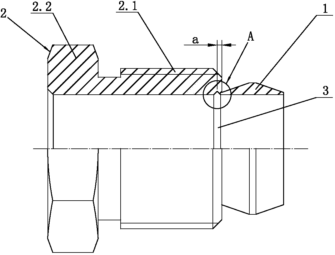
[0019] like figure 1 and figure 2 As shown, an integral ferrule joint with the following structure is provided, which includes a ferrule 1 and a pressure cap 2, the ferrule 1 is a ring structure, the pressure cap 2 is a cylindrical structure, and the pressure cap 2 is divided into threaded Part 2.1 and wrench holding part 2.2, the ferrule 1 is connected to the end position of the threaded part 2.1 and away from the wrench holding part 2.2, the axis of the ferrule 1 is on the same line as the axis of the threaded part 2.1, and The ferrule 1 and the threaded part 2.1 are of an integrated structure. The cross section of the ferrule 1 is a trapezoidal structure, and the inner surface of the ferrule 1 corresponds to the lower side of the trapezoidal structure. Generally, the centerline of the upper side and the lower side of the trapezoidal structure are in the on the same line.

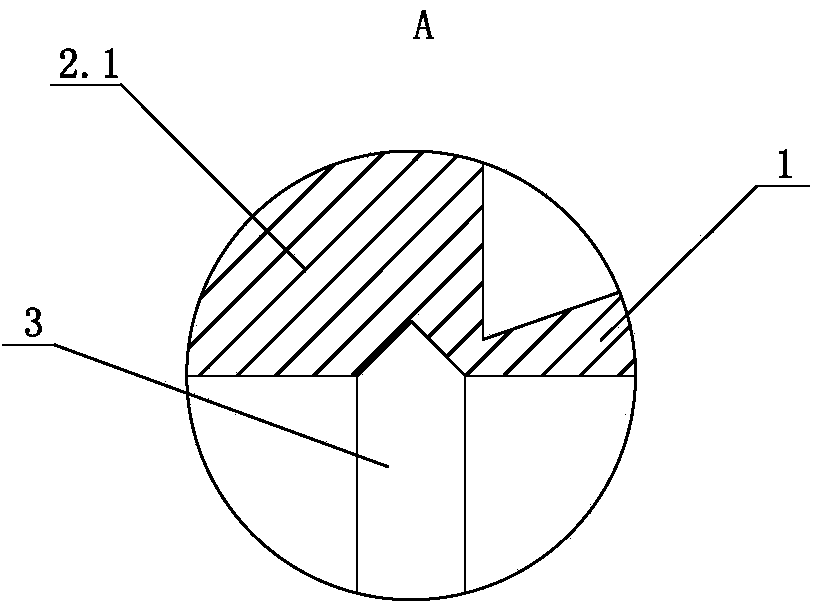
[0020] The inner wall of the threaded part 2.1 near the ferrule 1 is provided with an annular "V"-s...

Embodiment 2

[0025] An integral ferrule joint, which includes a ferrule 1 and a pressure cap 2, the ferrule 1 is a ring structure, the pressure cap 2 is a cylindrical structure, and the pressure cap 2 is divided into a threaded part 2.1 and a wrench clamping part 2.2, the ferrule 1 is connected to the end position of the threaded part 2.1 away from the wrench clamping part 2.2, the axis of the ferrule 1 and the axis of the threaded part 2.1 are on the same straight line, and the ferrule 1 and the threaded part 2.1 are One-piece structure, the cross-section of the ferrule 1 is a trapezoidal structure, and the inner surface of the ferrule 1 corresponds to the lower side of the trapezoidal structure. Generally, the midline of the upper side of the trapezoidal structure is on the same line as the midline of the lower side.

[0026] The inner wall of the threaded part 2.1 near the ferrule 1 is provided with an annular "V"-shaped groove 3, and the diameter corresponding to the bottom of the "V"-s...

Embodiment 3

[0031] An integral ferrule joint with the following structure, which includes a ferrule 1 and a pressure cap 2, the ferrule 1 is a ring structure, the pressure cap 2 is a cylindrical structure, and the pressure cap 2 is divided into a threaded part 2.1 and a wrench The clamping part 2.2, the ferrule 1 is connected to the end position of the threaded part 2.1 away from the wrench clamping part 2.2, the axis of the ferrule 1 and the axis of the threaded part 2.1 are on the same straight line, and the ferrule 1 and the thread Part 2.1 is an integrated structure. The cross-section of the ferrule 1 is a trapezoidal structure, and the inner surface of the ferrule 1 corresponds to the lower side of the trapezoidal structure. Generally, the midline of the upper side of the trapezoidal structure and the midline of the lower side are on the same straight line.

[0032] The inner wall of the threaded part 2.1 near the ferrule 1 is provided with an annular "V"-shaped groove 3, and the diam...


PUM


Abstract

The invention discloses an integral ferrule joint. The integral ferrule joint comprises a ferrule (1) and a pressing cap (2), wherein the pressing cap (2) is partitioned into a threaded portion (2.1) and a spanner clamping portion (2.2); the ferrule (1) is connected to the threaded portion (2.1) and far away from the end of the spanner clamping portion (2.2); the axis of the ferrule (1) and the axis of the threaded portion (2.1) are on the same straight line, and the ferrule (1) is integrated with the threaded portion (2.1); the cross section of the ferrule (1) has a trapezoidal structure, and the inner surface of the ferrule (1) corresponds to the lower side of the trapezoidal structure. Compared with the prior art, the integral ferrule joint has the characteristics of prevention of losing since the pressing cap and the ferrule can be placed and carried as an integral structure, high mounting efficiency, high connecting reliability and prevention of leakage.

Description

technical field [0001] The invention belongs to the technical field of connection joints, in particular to an integral ferrule joint used for pipeline connection. Background technique [0002] At present, when connecting low-pressure gas pipelines, the general method is to use (spherical or conical) ferrule connection. The ferrule joint in the prior art includes a ferrule and a pressure cap. When in use, the ferrule and the pressure cap are sequentially inserted onto the pipe fittings to be connected, and then the pipe fittings are connected to the pipe joint through the ferrule and the pressure cap. However, due to the split structure of the pressure cap and the ferrule, and the small size of the ferrule, they need to be placed and carried separately. In the process of actual use, the pressure cap or ferrule is easy to lose when placed and carried, which makes it impossible to install on site. At the same time, two steps are required for installation, and the installation ...

Claims


Application Information

Patent Timeline
Patent Type & Authority Applications(China)
IPC IPC(8): F16L25/00
CPCF16L15/08
Inventor 张枫张勤昌
Owner NINGBO WANAN
Why Eureka
Try Eureka