Programmable Controllers
A programming controller and sequential program technology, applied in the direction of program control, computer control, general control system, etc., can solve the problems of increased manufacturing cost and operating cost, and achieve the effect of improving positioning and visibility
- Summary
- Abstract
- Description
- Claims
- Application Information
AI Technical Summary
Problems solved by technology
Method used
Image

Examples
Embodiment approach 1
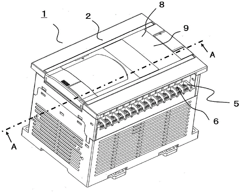
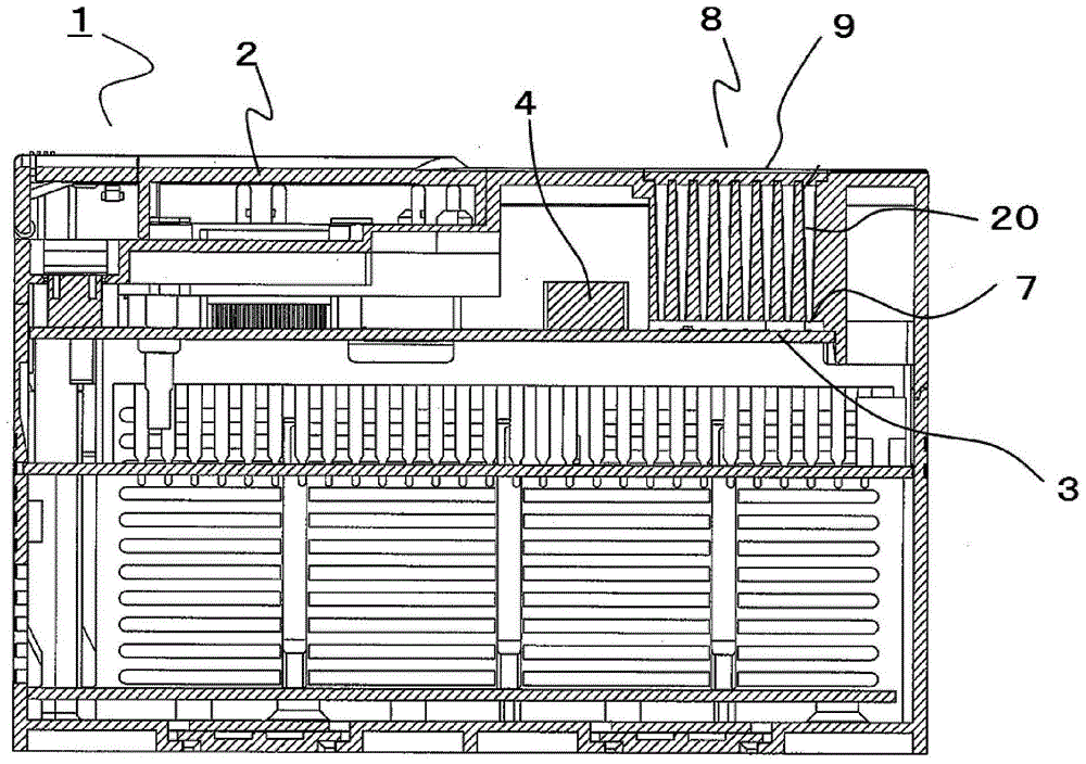
[0029] figure 1 It is an overall perspective view showing the programmable controller according to Embodiment 1 of the present invention, figure 2 is along figure 1 A cross-sectional view of line A-A in .
[0030] figure 1 and figure 2 Among them, a printed circuit board 3 of a programmable logic controller (programmable logic controller: programmable logic controller) 1 is mounted inside a resin case 2, and the printed circuit board 3 is equipped with an input unit, a storage unit, an output unit, and the like. various electronic components. In addition, a terminal terminal 5 is provided on the outer peripheral surface of the housing 2, and a plurality of input terminals and output terminals 6 connected to the input part and the output part are installed on the terminal terminal 5, so that it can be connected to a plurality of external devices, for complex sequence control.
[0031] On the other hand, in order to grasp the input state and input state of the above-ment...
Embodiment approach 2
[0056] Next, use Figure 7 , Embodiment 2 of the present invention will be described.
[0057] Figure 7 It is a plan view showing the light-transmitting protective plate 9 , and other configurations are the same as those in Embodiment 1, so description thereof will be omitted.
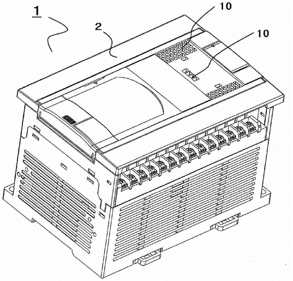
[0058] In the figure, the light-shielding surface 31 is formed on the upper surface of the light-transmitting protective plate 9 using ink as a light-shielding film to prevent light from the LED elements 7 from being emitted from the protective plate 9 . The light-shielding surface 31 is a light-shielding surface printed on the upper surface of the protective plate 9 made of resin by screen printing (silk screening, screen printing), and is formed on the protective plate 9 corresponding to the opening 10 of the housing 2 . The light-transmitting surface 32a trimmed by the light-shielding surface 31 is formed on the surface. Here, right above the opening 10 corresponding to the LED element 7, as if ...
Embodiment approach 3
[0068] Next, use Figure 8 , Embodiment 3 of the present invention will be described.
[0069] Figure 8 It is a plan view showing the light-transmitting protective plate 9 , and is a figure in which the light-shielding surface and the light-transmitting surface in Embodiment 2 are reversed. In addition, other configurations are the same as those in Embodiment 1, and thus description thereof will be omitted.
[0070] Figure 8 Among them, the first light-shielding surface 40 is formed on the upper surface of the light-transmitting protective plate 9 by using the ink used as a light-shielding film to prevent the light from the LED element 7 from passing outside the upper surface of the protective plate 9 corresponding to the opening 10. part of the shot. The first light-shielding surface 40 is formed at least around the area corresponding to the opening 10 on the upper surface of the protective plate 9, for example, the first light-shielding surface 40 may not be formed in ...
PUM
 Abstract
Description
Claims
Application Information
 - R&D
- Intellectual Property
- Life Sciences
- Materials
- Tech Scout
- Unparalleled Data Quality
- Higher Quality Content
- 60% Fewer Hallucinations
Browse by: Latest US Patents, China's latest patents, Technical Efficacy Thesaurus, Application Domain, Technology Topic, Popular Technical Reports.
© 2025 PatSnap. All rights reserved.Legal|Privacy policy|Modern Slavery Act Transparency Statement|Sitemap|About US| Contact US: help@patsnap.com