Three-phase permanent-magnet synchronous motor rotor punching sheet suitable for both line starting and variable frequency starting

A technology of rotor punching and variable frequency starting, which is applied to synchronous machine parts, magnetic circuit rotating parts, magnetic circuit shape/style/structure, etc., can solve the problem of reduced power factor of permanent magnet motor and unreasonable rotor punching design , the permanent magnet motor has low overload capacity, etc., to achieve reasonable no-load back electromotive force, obvious power saving effect, and small vibration effect.

Inactive Publication Date: 2014-10-01
JIANGSU JIUZHI MOTOR TECH
View PDF5 Cites 7 Cited by
  • Summary
  • Abstract
  • Description
  • Claims
  • Application Information

AI Technical Summary

Problems solved by technology

[0002] Currently commonly used permanent magnet motor rotor punching, due to the unreasonable design of the rotor punching, the overload capacity of the permanent magnet motor is low, resulting in frequent out-of-step and burning of the permanent magnet motor; The operation of the motor is not stable enough; cracks are generated in the magnetic steel during operation, which reduces the power factor of the permanent magnet motor, increases the armature current, increases the copper consumption of the stator, reduces the efficiency, the power saving effect is not ideal, and the electromotive force decreases during operation, resulting in active energy consumption. power rate drop

Method used


Image

  • Three-phase permanent-magnet synchronous motor rotor punching sheet suitable for both line starting and variable frequency starting
  • Three-phase permanent-magnet synchronous motor rotor punching sheet suitable for both line starting and variable frequency starting
  • Three-phase permanent-magnet synchronous motor rotor punching sheet suitable for both line starting and variable frequency starting

Examples


Embodiment Construction

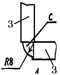
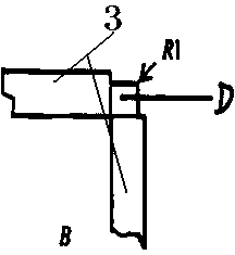
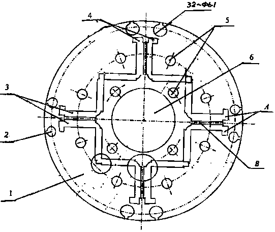
[0037] Refer to attached figure 1 , 2 , 3. The common three-phase permanent magnet synchronous motor rotor stamping structure for line start and variable frequency start has a rotor stamping body 1, and the outer circumference of the rotor stamping body 1 is evenly distributed with a starting rod hole 2, and a rotor punching plate is placed below the starting rod hole 2 The body 1 is evenly distributed with W-shaped magnetic steel slots 3. A magnetic isolation bridge A is set under the start rod hole 2 and above the magnetic steel slot 3. A magnetic isolation bridge B is set between two radial magnetic steel slots. A magnetic isolation bridge C is arranged between the magnetic steel grooves, 12 rigidity-enhancing screw holes 5 are arranged on the rotor punching body 1, a rotor shaft hole 6 is arranged in the middle of the rotor punching body 1, and the magnetic steel groove 3 is W-shaped.

[0038] The rotor punch body 1 has a diameter of Φ134-134.03mm.

[0039] The diameter ...


PUM


Abstract

The invention relates to a three-phase permanent-magnet synchronous motor rotor punching sheet suitable for both line starting and variable frequency starting. The three-phase permanent-magnet synchronous motor rotor punching sheet is an iron core punching sheet which is super-ultra-high in efficiency and suitable for a rotor of a high pull-out torque three-phase rare-earth permanent magnet synchronous motor and a rotor of a variable-frequency and variable-speed motor three-phase permanent magnet synchronous motor, and is used for a permanent magnet synchronous motor with a 132 base. The three-phase permanent-magnet synchronous motor rotor punching sheet is provided with a rotor punching sheet body made of a low-loss silicon steel sheet in a punching mode. Starting rod holes are evenly distributed on the outer circumference of the rotor punching sheet body, and W-shaped magnetic steel grooves are evenly formed in the rotor punching sheet body. A magnetic isolation bridge A is arranged between the lower portions of the starting rods and the magnetic steel grooves, and a magnetic isolation bridge B and a magnetic isolation bridge C are arranged between every two adjacent magnetic steel grooves. Rigidity reinforced screw holes and rotor shaft holes are formed in the rotor punching sheet body.

Description

technical field [0001] The present invention relates to a common three-phase permanent magnet synchronous motor rotor stamping for line starting and variable frequency starting, which is a common three-phase permanent magnet synchronous motor rotor stamping for line starting and variable frequency starting, which belongs to ultra-ultra-high efficiency and high out-of-step torque The common iron core punching sheet for the rotor of the three-phase rare earth permanent magnet synchronous motor and the variable frequency speed regulating three-phase permanent magnet synchronous motor is used for the permanent magnet synchronous motor with 132 frames. Background technique [0002] Currently commonly used permanent magnet motor rotor punching, due to the unreasonable design of the rotor punching, the overload capacity of the permanent magnet motor is low, resulting in frequent out-of-step and burning of the permanent magnet motor; The operation of the motor is not stable enough; ...

Claims


Application Information

Patent Timeline
Patent Type & Authority Applications(China)
IPC IPC(8): H02K1/27H02K21/02
Inventor 孙建新胥建华
Owner JIANGSU JIUZHI MOTOR TECH
Why Eureka
Try Eureka