Torsional oscillation damping device

A technology of torsional vibration and attenuation devices, which is applied in transmission devices, rotation vibration suppression, fluid transmission devices, etc., can solve the problems of reduced vibration attenuation performance, failure to obtain vibration attenuation performance, increased man-hours or manufacturing costs, etc., to achieve vibration suppression and abnormal noise effects

Inactive Publication Date: 2014-10-01
TOYOTA JIDOSHA KK
View PDF7 Cites 12 Cited by
  • Summary
  • Abstract
  • Description
  • Claims
  • Application Information

AI Technical Summary

Problems solved by technology

On the other hand, if instead of ensuring such a space, the amplitude of the mass body is forcibly suppressed by a stopper plate, etc., the size of the device can be avoided, but the number of reciprocating motions of the mass body will change, and there is a problem that it cannot be obtained. Possibility of expected vibration damping performance
In addition, there is a possibility that man-hours and manufacturing costs will increase due to an increase in the number of parts
On the other hand, although it is also considered to reduce the mass body so that the mass body does not protrude outward compared with the outer peripheral edge of the rotating body, if this method is adopted, there is a possibility that the mass body will be insufficient and the vibration damping performance will be reduced. possibility

Method used


Image

  • Torsional oscillation damping device
  • Torsional oscillation damping device
  • Torsional oscillation damping device

Examples


Embodiment Construction

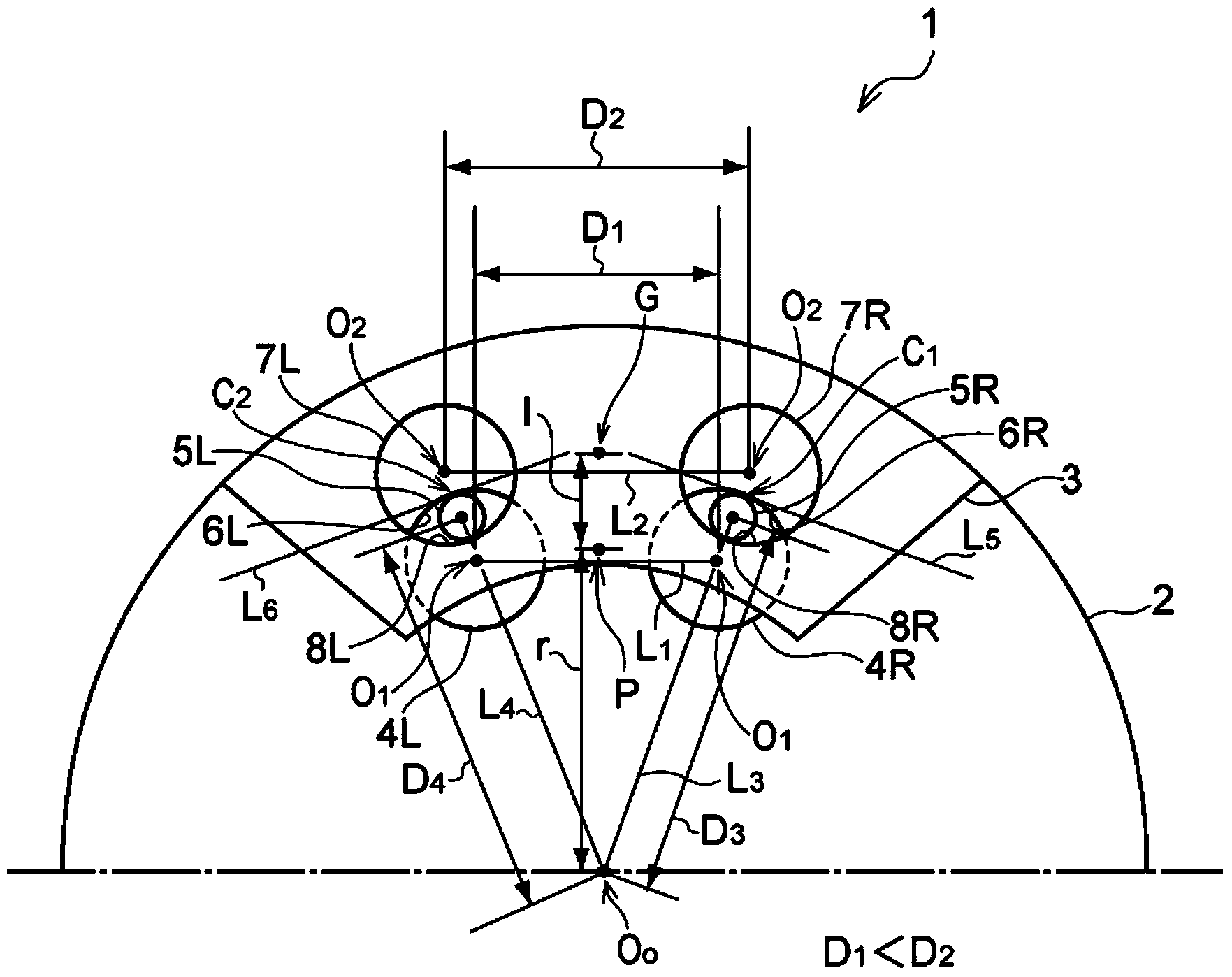
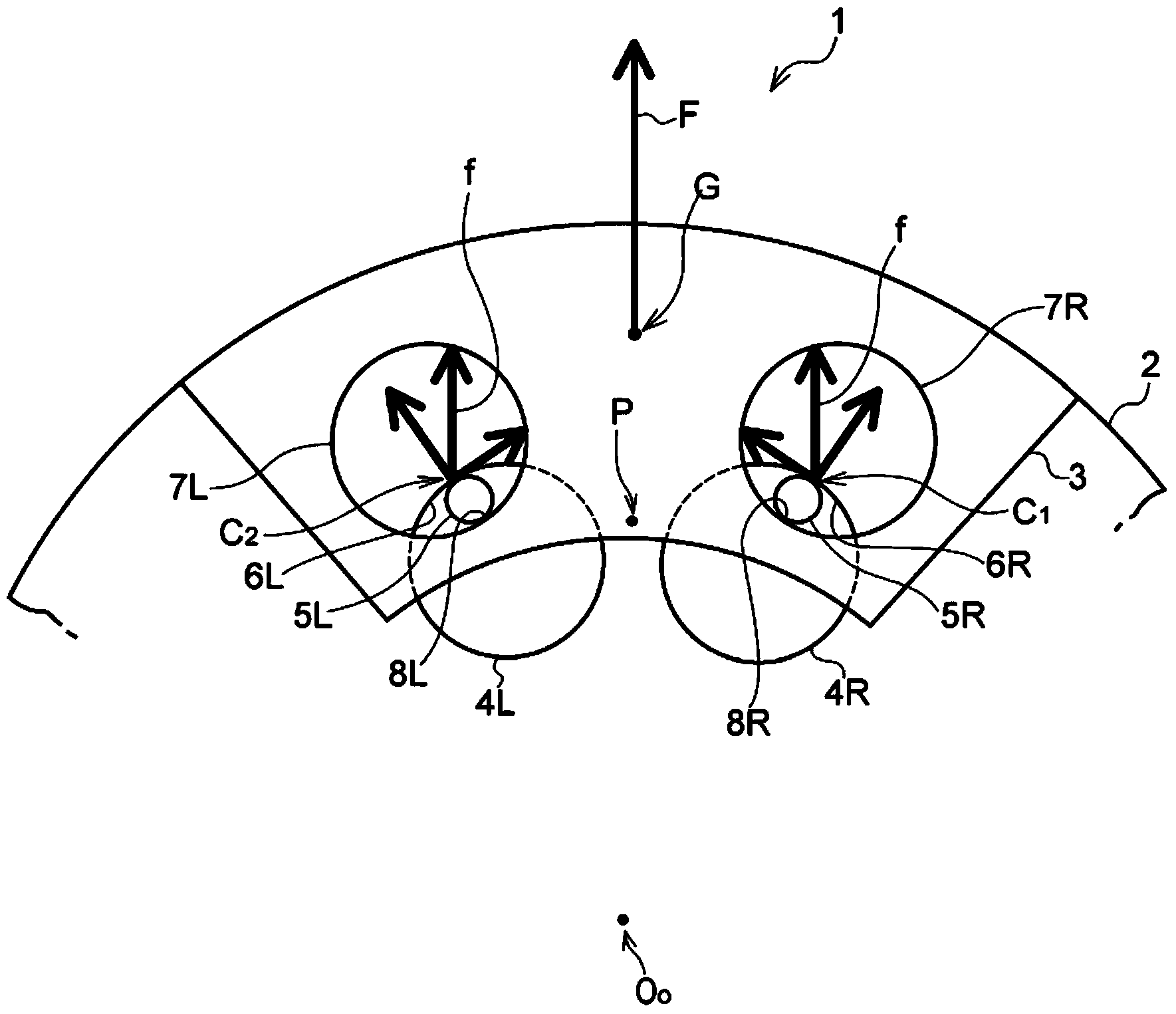
[0026] Next, this invention is demonstrated more concretely. figure 1 It is a partially enlarged view showing an example of the torsional vibration damping device 1 according to the present invention, and schematically illustrates the centrifugal force acting on the mass body 3 mounted so as to be able to swing relative to the rotating body 2 , and the force toward the circumferential direction of the rotating body 2 does not act on the mass body 3 . The rotating body 2 is, for example, a disk-shaped member, and is configured to rotate integrally with a rotating shaft such as an output shaft of an engine or an input shaft of a transmission, not shown. exist figure 1 In the illustrated example, a pair of first hollow portions 4R, 4L are formed on the outer peripheral side of the rotating body 2 at a predetermined interval in the circumferential direction. Each of the first hollow portions 4R, 4L is formed in a hollow cylindrical shape as an example. The center of curvature o...


PUM


Abstract

Provided is a torsional oscillation damping device with which space for a mass that moves in a reciprocating manner can be maintained and the oscillation-damping effect can be improved. This torsional oscillation damping device, wherein a mass (3) is attached to a rotating body (2) by means of two support pins (5R, 5L), is equipped with: two first hollow parts (4), which are formed in the rotating body (2) at positions corresponding to the support pins (5R, 5L), and into which the support pins (5R, 5L) are inserted; and two second hollow parts (7), which are formed in the mass (3) at positions opposing the first hollow parts (4), and into which the support pins (5R, 5L) are inserted. The portions of the inner circumferential edges of the first hollow parts (4) which are to the outside in the radial direction of the rotating body (2) are guide surfaces (6R, 6L), and the portions of the inner circumferential edges of the second hollow parts (7) which are to the inside in the radial direction of the rotating body (2) are attachment surfaces (8R, 8L). The guide surfaces (6R, 6L) and the attachment surfaces (8R, 8L) are formed as concave curved surfaces, with the distance (D1) between the centers of curvature (O1) of the guide surfaces (6R, 6L) being shorter than the distance (D2) between the centers of curvature (O2) of the attachment surfaces (8R, 8L).

Description

technical field [0001] The present invention relates to a device for attenuating torsional vibration of a rotating body such as a crankshaft or a power transmission shaft, and more particularly to a device configured in such a manner that a rotating body is mounted with a The reciprocating mass body damps the torsional vibration of the rotating body through the reciprocating motion of the mass body. Background technique [0002] A rotating body such as a drive shaft used to transmit torque generated by a driving force source has fluctuations in the input torque itself or the torque used to drive equipment connected to the rotating body When vibration occurs due to fluctuations, etc. Such a torque fluctuation phase acts on the rotating body as torsional vibration. A device for damping torsional vibrations of such a rotating body has been developed. An example thereof is described in JP-A-2011-504987 and JP-A-2011-504986. [0003] In the dynamic vibration absorbers describ...

Claims


Application Information

Patent Timeline
Patent Type & Authority Applications(China)
IPC IPC(8): F16F15/14F16F15/10F16F15/131F16H45/02
CPCF16F15/145F16H2045/0263F16H2045/0205F16H45/02F16H2045/0226F16H2045/0294
Inventor 堀田修平宫原悠相岛慎吾
Owner TOYOTA JIDOSHA KK
Why Eureka
Try Eureka