Torque-Transmission Device

Active Publication Date: 2019-07-25
ZF FRIEDRICHSHAFEN AG
View PDF8 Cites 7 Cited by
  • Summary
  • Abstract
  • Description
  • Claims
  • Application Information

AI Technical Summary

Benefits of technology

[0006]Therefore, it is an object of one aspect of the present invention to provide a torque transmission device in w

Problems solved by technology

However, it is disadvantageous in this torque transmission device known from the prior art that the individual components, which are responsible for reducing torsional vibrations a

Method used


Image

  • Torque-Transmission Device
  • Torque-Transmission Device
  • Torque-Transmission Device

Examples


Embodiment Construction

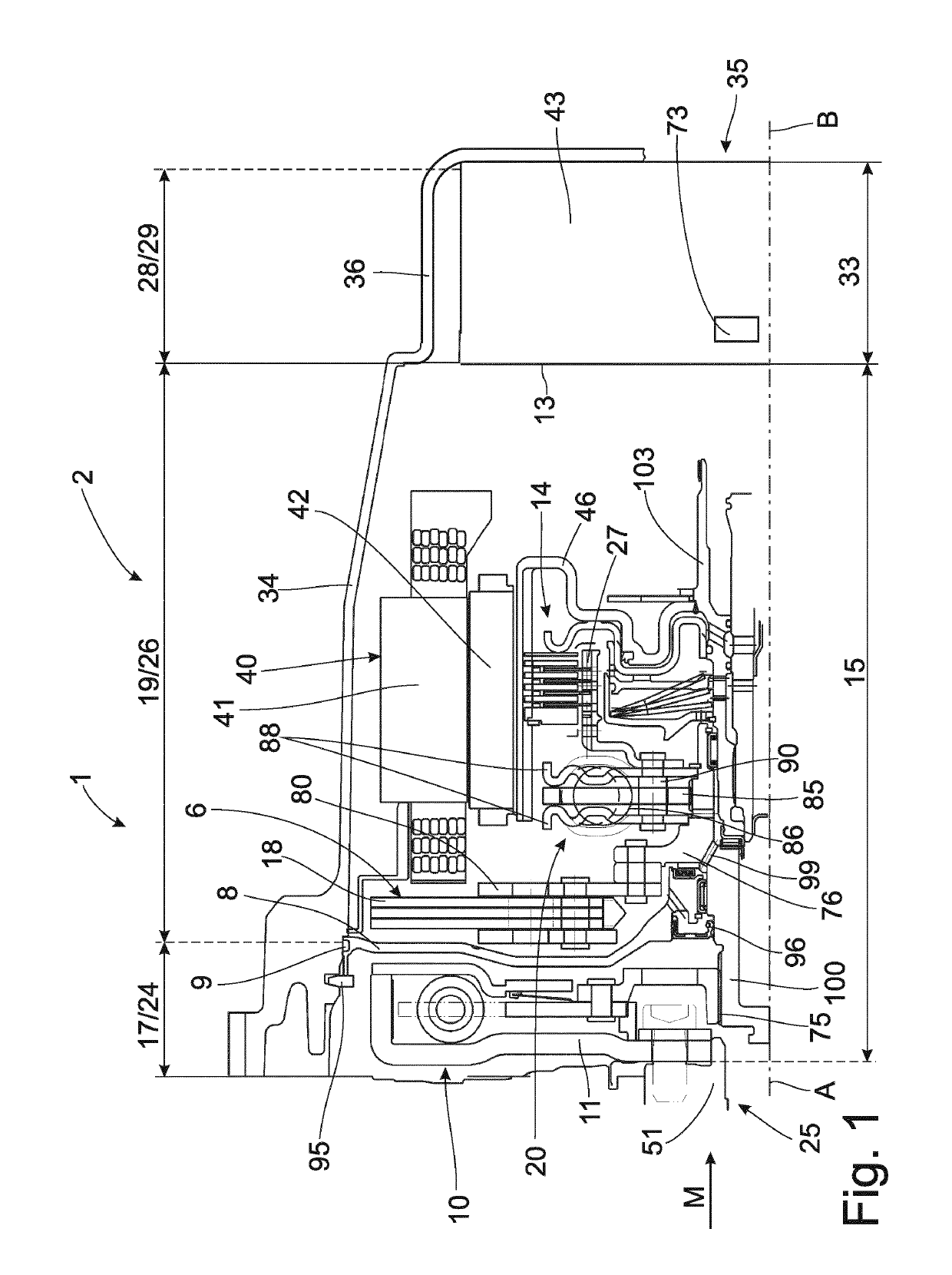
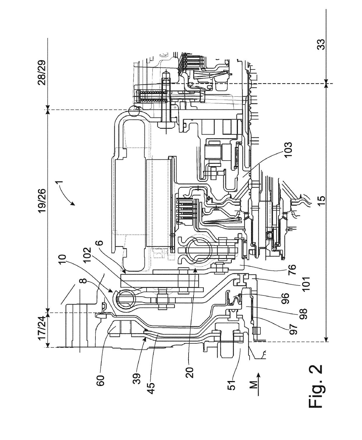
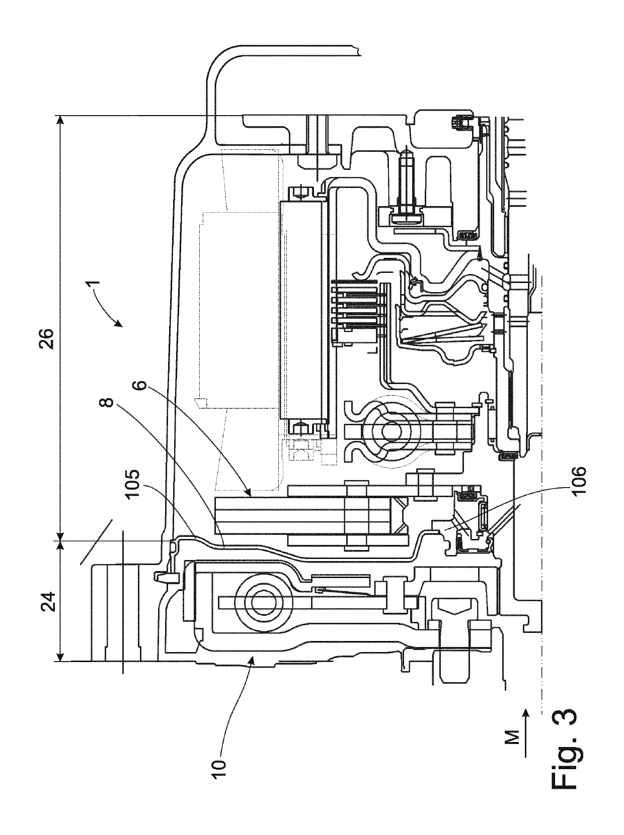
[0032]FIG. 1 shows a torque transmission arrangement 1 for an automatic hybrid transmission 2. A basic construction is as follows in a sequence of a torque path M from an input area 25 which can be formed, for example, by an internal combustion engine to an output area 35, which can be formed, for example, by an output shaft of a transmission. The torque transmission arrangement is divided into three spatial areas. A first spatial area 17, which may also be referred to as dry space 24, a subsequent second spatial area 19, which may also be referred to as moist space 26 and a subsequent third spatial area 28 which may also be referred to as wet space 29. A first torsional damper 10 is located in the first spatial area 17 and is constructed as a dual mass flywheel. This first torsional damper 10 can be operated with a grease filling and is preferably placed in the dry space, which does not contain any viscous medium. The second torsional damper 20 is integrated in the second spatial a...


PUM


Abstract

A torque transmission device for a powertrain of a motor vehicle has an input area and an output area. A torque path runs from the input area to the output area. A torsional vibration damping unit is positioned first, followed by a gear unit, along the torque path between the input area and the output area. The torsional vibration damping unit provides a first spatial area and an adjoining second spatial area along the torque path, and the gear unit provides an adjoining third spatial area.

Description

CROSS REFERENCE TO RELATED APPLICATIONS[0001]This is a U.S. national stage of application No. PCT / EP2017 / 062836, filed on May 29, 2017. Priority is claimed on German Application No. DE102016211945.1, filed Jun. 30, 2016, the content of which is incorporated here by reference.BACKGROUND OF THE INVENTION1. Field of the Invention[0002]The present invention is directed to a torque transmission device for a powertrain of a motor vehicle with an input area formed principally by an internal combustion engine, a downstream torsional vibration damping unit, a transmission arrangement, and a downstream output area formed principally by a transmission output shaft.2. Description of the Prior Art[0003]A torque transmission device in which a torsional vibration damping arrangement with a mass damper in a housing area is provided between a drive unit and a gear unit is known from the prior art in DE 10 2014 206 330 A1.[0004]US 2011259698 AA also shows a torque transmission device with a torsional...

Claims


Application Information

Patent Timeline
IPC IPC(8): F16F15/123F16H57/02F16F15/14B60K6/387B60K6/40
CPCF16F15/12353F16H57/02F16F15/145F16F15/123B60K6/387B60K6/40B60Y2200/92B60Y2400/48F16H57/028B60K2006/4825F16H2057/02086F16H2057/0216B60K6/48F16D25/0638Y02T10/62
Inventor WEBERPITTNER, DANIELHAMMER, PETERSTROM, ALEXANDERSIEMENS, KYRILLEINENKEL, STEFFENFREY, PETERGROSSPIETSCH, WOLFGANGSASSE, CHRISTOPHHERTEL, MARTINMANGER, ALEXANDER
Owner ZF FRIEDRICHSHAFEN AG
Why Eureka
Try Eureka