Wet clutch for a motorcycle

a wet clutch and motorcycle technology, applied in the field of wet clutches, can solve the problems of variable clamping force of coil springs, high mass moment of inertia, and relatively complex production of friction clutches, so as to reduce load change reactions or attenuate torsional vibration, reduce production costs, and improve the manufacturing quality of friction clutches

Active Publication Date: 2014-04-17
SCHAEFFLER TECH AG & CO KG
View PDF8 Cites 7 Cited by
  • Summary
  • Abstract
  • Description
  • Claims
  • Application Information

AI Technical Summary

Benefits of technology

[0011]In an embodiment, the starter gear can be integrated with a plain bearing bush for supporting the outer basket. In this way, the outer basket can be realized in a compact, production- and installation-friendly manner. By providing the starter gear near the bearing bush, the starter gear can be dimensioned with a relatively small circumference, which can be exploited to match an actuation travel distance of the foot pedal to a torsional angle of the wet clutch, and thus, a crank angle of the drive engine.
[0012]In an embodiment, the clamping element includes a membrane spring. The membrane spring can likewise be made from a sheet metal part. Through the use of similar procedural steps to produce the membrane spring and at least one of the clutch baskets, fabrication quality of the friction clutch can be improved overall, thus reducing production costs.
[0013]In another embodiment, an elastic element is provided for torsionally elastic connection of the outer basket to the assigned toothing element. This makes it possible to implement a shock absorber, which can contribute to reducing load change reactions or attenuating torsional vibrations, which may be introduced into the wet clutch, for example, by the drive engine.
[0014]The elastic element includes a number of radial sheet metal straps. This enables the use of sheet steel as a source material for producing the wet clutch to be extended consistently to the elastic element, which can result in additional advantages in the production technique. In one embodiment, the sheet metal straps can be designed in a single piece with one of the two clutch baskets.
[0015]The outer basket can include an additional encircling ring to support the outer basket under centrifugal force loading, thus reducing the danger of the outer basket bending or breaking under high speeds of rotation. In this way, an additional safety reserve can be provided, without having to significantly increase expense with regard to the material used or the production of the wet clutch.
[0016]In an embodiment, a device for producing an axial pre-tensioning on the clamping element is provided, in order to compensate for a decrease in the height of the stacked first and second frictional elements which is a function of wear. For example, in comparison to a conventional clutch having coil springs, in this way an actuation travel distance needed to operate the clutch can be kept essentially constant over the life of the frictional elements. This eliminates the need for an external mechanism to compensate for a corresponding actuation play, for example, a manually-operated mechanism; thus making it possible to increase the reliability of use of the wet clutch, or of a vehicle in which the wet clutch is used.

Problems solved by technology

This clutch is relatively complicated to produce, has a high mass moment of inertia, and the clamping force of the coil springs varies over a decrease in height of the friction disks which is a function of wear.

Method used


Image

  • Wet clutch for a motorcycle
  • Wet clutch for a motorcycle
  • Wet clutch for a motorcycle

Examples


embodiment v1

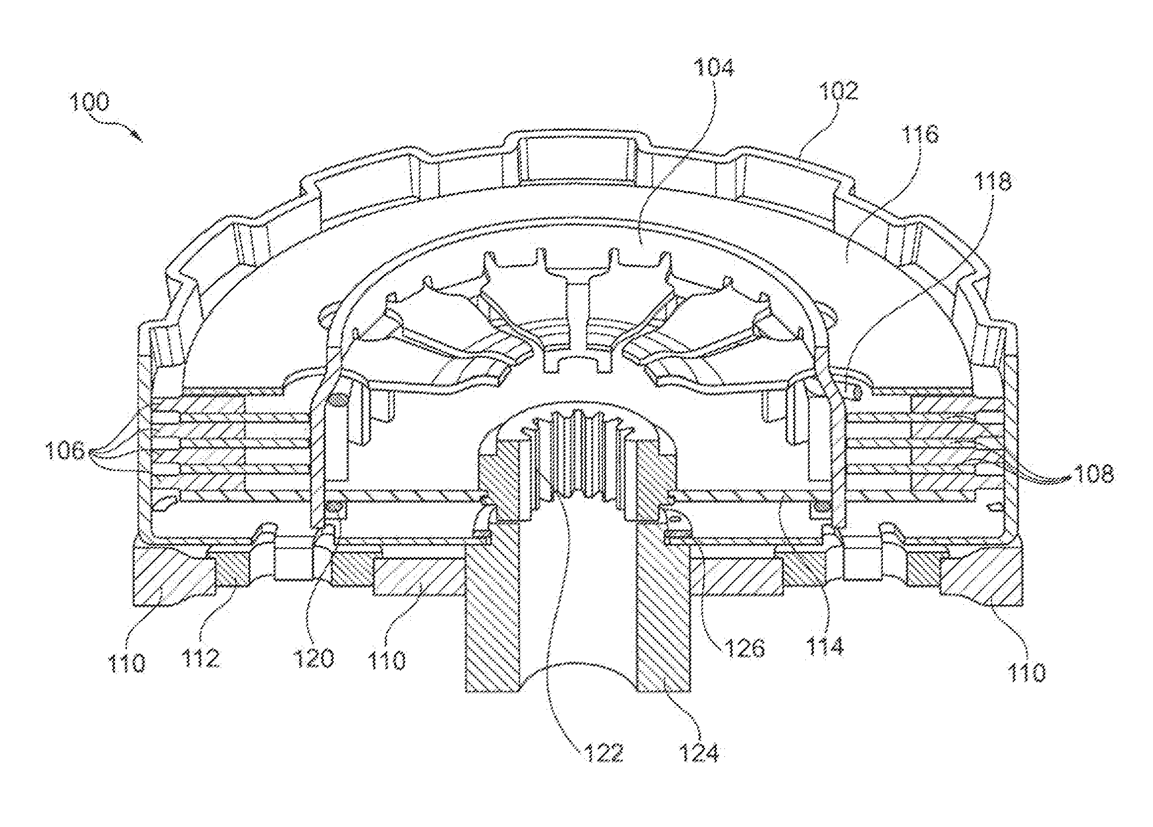
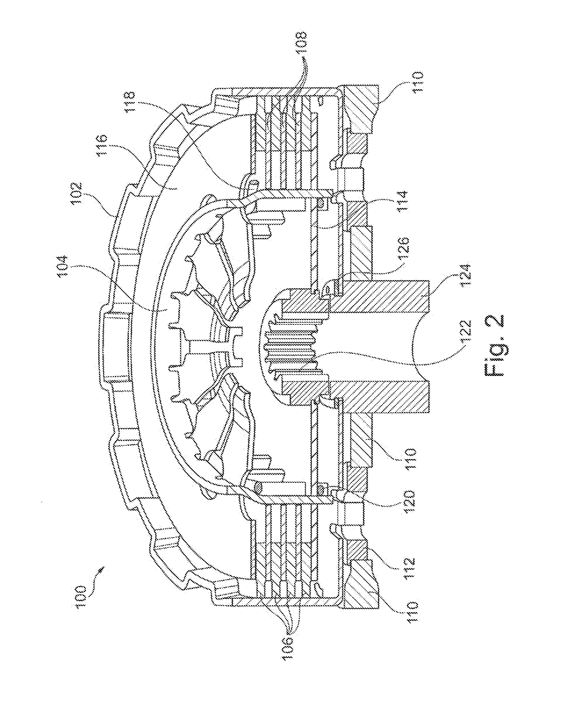
[0036]FIG. 2 shows wet clutch 100 for use in a motorcycle, in particular in a lightweight motorcycle having a reciprocating internal combustion engine with one or more cylinders and a cylinder capacity of approximately 170-250 cm3, for example, approximately 200 cm3. Wet clutch 100 includes outer basket 102, inner basket 104, friction disks 106, laminae 108, primary gear 110, shock absorbers 112, floor plate 114, lamellar spring 116, supporting wire 118, closing wire 120, output hub 122, bearing bush 124 and locking ring 126. A torque of a drive engine can be introduced into wet clutch 100 via primary gear 110. A pinion that meshes with primary gear 110 normally sits directly on a crankshaft of the drive engine. Primary gear 110 includes cutouts into which shock absorbers 112, which are designed as elastic elements are introduced. Each shock absorber 112 has an additional cutout, with which a corresponding axial strap of outer basket 102 engages.

[0037]A number of friction disks 108 ...

embodiment v2

[0052]Embodiment V2 is based on embodiment V1, and differs essentially in the attachment of floor plate 114 to inner carrier 142. The rest of the features named above in reference to embodiment V1 are unchanged.

[0053]FIG. 10 shows wet clutch 100 of embodiment V2 in a view corresponding to FIG. 2.

[0054]FIG. 11 shows the attachment of floor plate 114 to inner carrier 142. The cutouts in U-shaped profiles 148 of inner carrier 142, which receive closing wire 120 in embodiment V1 (see FIG. 9), are changed in embodiment V2 in such a way that floor plate 114 can be set on profiles 148 and rotated around the axis of rotation of wet clutch 100 so that an axial securing of floor plate 114 on inner carrier 142 develops. Floor plate 114, and in particular, its U-shaped cutouts to receive profiles 148, do not differ from those of embodiment V1. Depending on the design of the cutouts on profiles 148 of inner carrier 142, floor plate 114 is secured on inner carrier 142 by turning it clockwise or c...

embodiment v3

[0056]Embodiment V3 is based on embodiment V1, and differs from the latter essentially in the toothing of outer basket 102, the additional structure and producibility of outer basket 102, and shock absorbers 112.

[0057]FIG. 12 shows wet clutch 100 in a depiction corresponding to FIG. 2. it differs from the latter in that primary gear wheel 110 is designed as a ring gear, a torsional connection of ring gear 110 to outer basket 102 being produced by a positive lock with the meandering external profile of outer basket 102.

[0058]A floor section of outer basket 102 is formed by ten webs 154, which extend radially inward as far as bearing bush 124. Shock absorbers 112 are implemented by twelve U-shaped spring elements, which make an elastic transfer of torque possible between ring gear 110 and outer basket 102.

[0059]FIG. 13 shows outer basket 102 with ring gear 110 and shock absorbers 112. In reference to the depiction in FIG. 12, the depicted sub-assembly is turned upside-down. Outer bask...


PUM


Abstract

A wet clutch for a motorcycle having an outer basket having a first toothing as the input side of the wet clutch, an inner basket which is coaxial to the outer basket having a second toothing as the output side of the wet clutch, first frictional elements which are torsionally connected to the outer basket, second frictional elements which are torsionally connected to the inner basket, the first and second frictional elements being situated axially alternating between the inner basket and the outer basket, and a clamping element to compress the first and second frictional elements axially in order to produce a torsional connection between the input side and the output side. The inner basket and/or the outer basket can essentially be produced from one or more sheet metal parts.

Description

CROSS-REFERENCE TO RELATED APPLICATIONS[0001]This patent is filed under 35 U.S.C. §120 and §365(c) as a continuation of International Patent Application No. PCT / DE2012 / 000651 filed Jun. 28, 2012, which application claims priority from German Patent Application No. 10 2011 106 021.2 filed Jun. 30, 2011, which applications are incorporated herein by reference in their entireties.FIELD OF THE INVENTION[0002]The invention relates to a wet clutch, and in particular, to a multiple-disk wet clutch for a motorcycle.BACKGROUND OF THE INVENTION[0003]A wet clutch for a motorcycle normally includes an inner basket and an outer basket, which are situated coaxially on a main transmission shaft. A number of first friction disks are engaged with the outer basket and a number of second friction disks are engaged with the inner basket, the first and second friction disks being situated coaxially in alternating order.[0004]A frictional lock can be produced selectively between the inner basket and the ...

Claims


Application Information

Patent Timeline
Patent Type & Authority Applications(United States)
IPC IPC(8): F16D13/52
CPCF16D13/52F16D13/646F16D13/683F16D2300/12
Inventor RABER, CHRISTOPHGANTER, RAINERCHAMBRION, MARTINKELLER, MARIONDECKER, FLORIANRITTER, RAIMUNDSTOELZE, JUERGENSPERBER, MATTHIASKOZLOWSKI, FRANKRAATZ, JOACHIM
Owner SCHAEFFLER TECH AG & CO KG
Why Eureka
Try Eureka