Flywheel and gear ring component

A flywheel and ring gear technology, which is applied in the field of flywheel and ring gear components, can solve the problems of affecting the life of bearing bushes and related parts, and not doing overall balance, so as to achieve the effects of simple and reasonable structure, reducing torsional vibration, and facilitating manufacturing and processing

Inactive Publication Date: 2014-07-30
GUANGXI YUCHAI MASCH CO LTD
View PDF6 Cites 7 Cited by
  • Summary
  • Abstract
  • Description
  • Claims
  • Application Information

AI Technical Summary

Problems solved by technology

[0005] However, the flywheel and ring gear assembly and the crankshaft are only dynamically balanced for a single unit, not the overall balance. After the flywheel, ring gear assembly and crankshaft are assembled, there will still be a certain amount of dynamic unbalance, which will still affect the life of the bearing bush and related parts.

Method used


Image

  • Flywheel and gear ring component
  • Flywheel and gear ring component
  • Flywheel and gear ring component

Examples


Embodiment Construction

[0026] The specific embodiments of the present invention will be described in detail below with reference to the accompanying drawings, but it should be understood that the protection scope of the present invention is not limited by the specific embodiments.

[0027] Unless otherwise expressly stated otherwise, throughout the specification and claims, the term "comprising" or its transformations such as "including" or "including" will be understood to include the stated elements or components, and not Other elements or other components are not excluded.

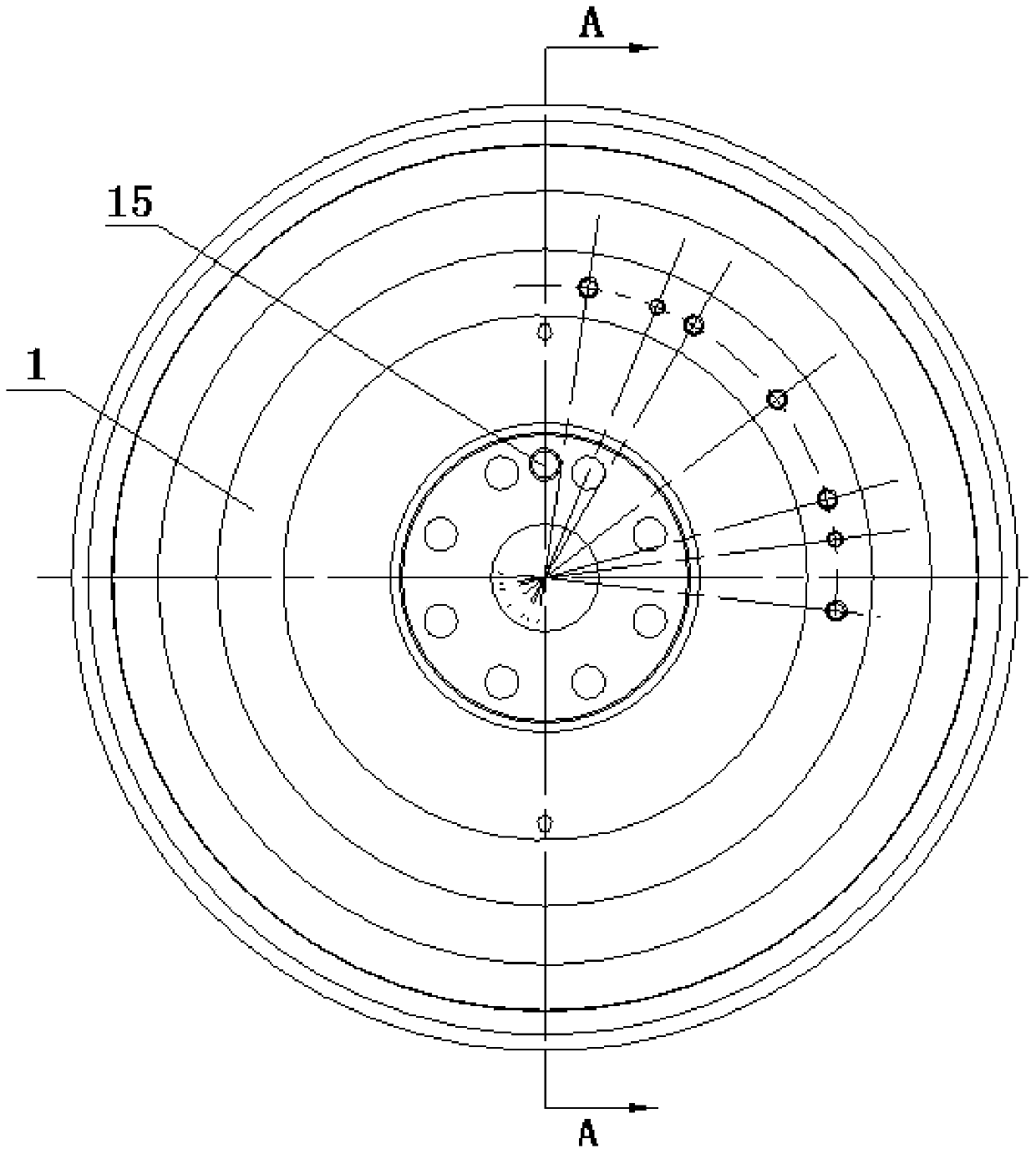
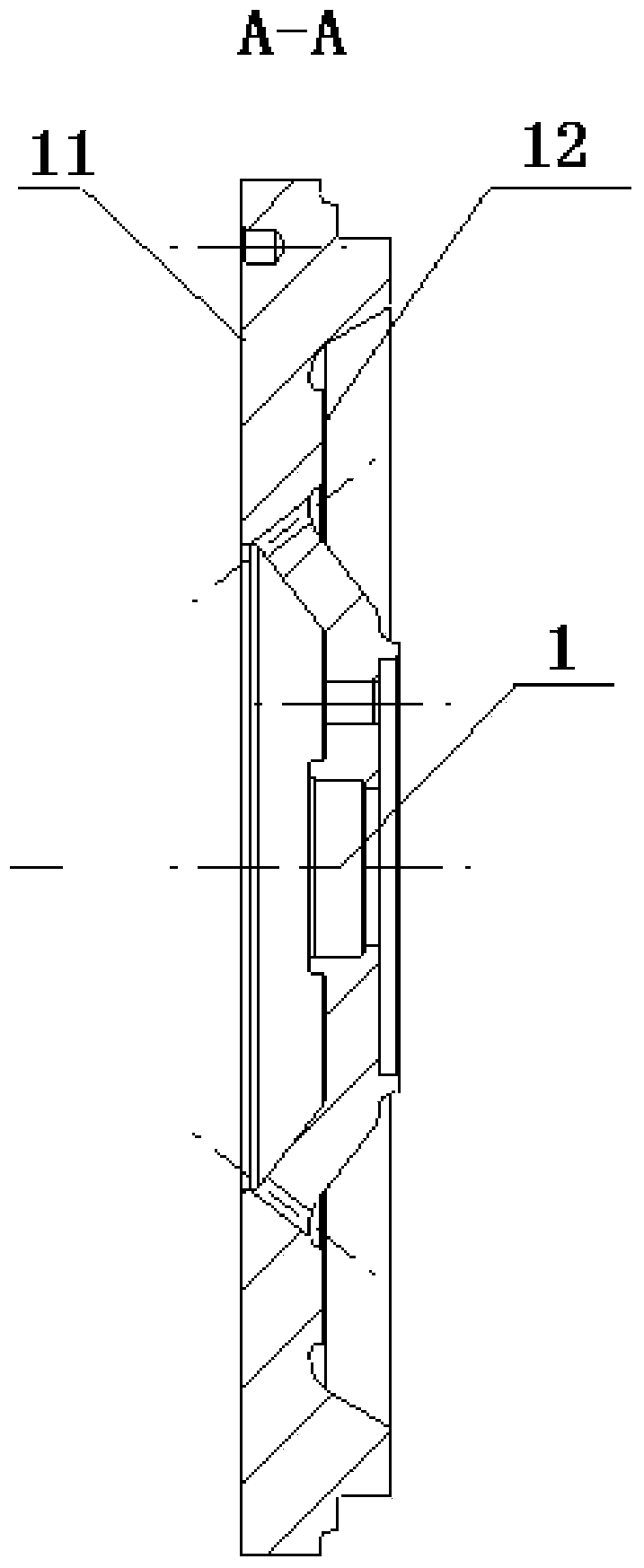
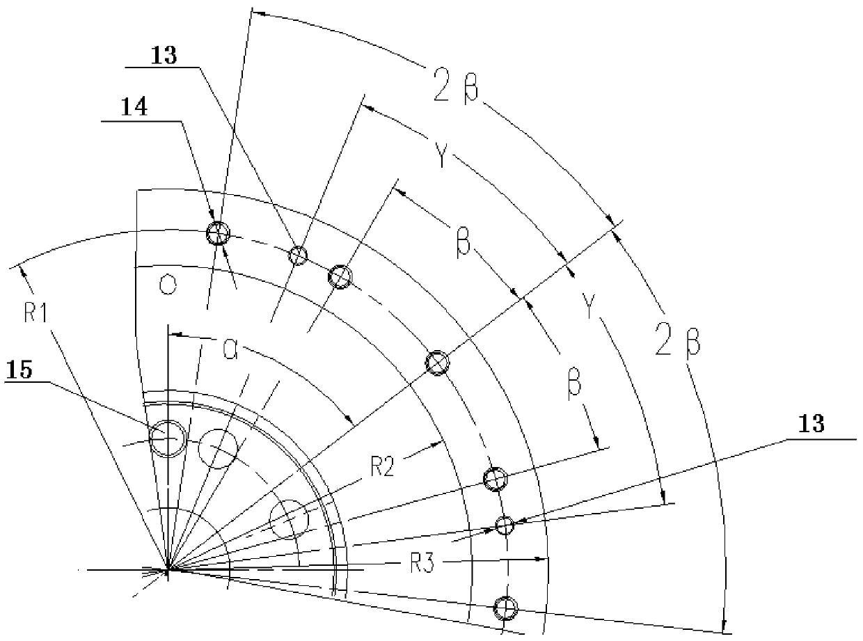
[0028] Such as Figure 6 to Figure 8 As shown, the flywheel and ring gear assembly according to the specific embodiment of the present invention is mainly used in multi-cylinder engines, especially V-type engines. The specific structure includes: flywheel 1 and ring gear 2, and counterweights arranged on flywheel 1. 3. The counterweight 3 is distributed to the flywheel 1 as a counterweight, which greatly reduces the size and numbe...


PUM


Abstract

The invention discloses a flywheel and gear ring component. The flywheel and gear ring component comprises a flywheel, a gear ring and a counterweight, wherein the rear end surface of the flywheel is a mounting combined surface of a clutch; the front end surface of the flywheel is a counterweight mounting surface; the flywheel is provided with a counterweight mounting and positioning pin hole and a counterweight mounting threaded hole; the counterweight is arranged on the flywheel by a bolt, and is positioned with the flywheel through a positioning pin. The flywheel and gear ring component is simple and reasonable in structure; the size and the number of the balancing blocks on a crank shaft are greatly reduced by distributing balancing blocks to the flywheel; the market requirements of miniaturization and lightweight of an engine are met; meanwhile, the manufacturing and the machining of the crank shaft are facilitated; the production cost of the crank shaft is reduced; the torsional vibration caused by the dynamic unbalance of a crank shaft system is reduced by the flywheel and gear ring component and the overall balancing process of the crank system, and service lives of a bearing bush and related parts are prolonged.

Description

Technical field [0001] The invention relates to the field of engines, in particular to a flywheel and ring gear assembly. Background technique [0002] In the engine structure, the crank connecting rod mechanism, which is one of the two major engine mechanisms, has a basic structure including a piston connecting rod assembly, a pulley assembly, a crankshaft assembly, and a flywheel and ring gear assembly. Its function is to expand the combustion gas and push the piston to do work. The linear motion of the piston is transformed into the rotational motion of the crankshaft, and the mechanical work is output from the flywheel at the rear end of the crankshaft. [0003] The crankshaft is one of the most important parts of the engine. The entire power of the engine is output through the crankshaft. The crankshaft works under the combined action of constantly changing forces and moments (including bending moments and torques). Additional torsion stress caused by torsion. In order to re...

Claims


Application Information

Patent Timeline
Patent Type & Authority Applications(China)
IPC IPC(8): F16F15/31
Inventor 余锦海覃文苏怀林胡国强覃壮革向本杰尹光跃
Owner GUANGXI YUCHAI MASCH CO LTD
Why Eureka
Try Eureka