Wireless communication terminal device and method for controlling transmission power

A wireless communication terminal and transmission power technology, applied in wireless communication, power management, multiplexing communication, etc., can solve the problem of not supporting simultaneous transmission of PUCCH and SRS

Active Publication Date: 2014-10-01
PANASONIC INTELLECTUAL PROPERTY CORP OF AMERICA
View PDF6 Cites 28 Cited by
  • Summary
  • Abstract
  • Description
  • Claims
  • Application Information

AI Technical Summary

Problems solved by technology

In addition, in the CA of Rel.10, the simultaneous trans

Method used


Image

  • Wireless communication terminal device and method for controlling transmission power
  • Wireless communication terminal device and method for controlling transmission power
  • Wireless communication terminal device and method for controlling transmission power

Examples


Embodiment approach 1

[0061] [Structure of base station]

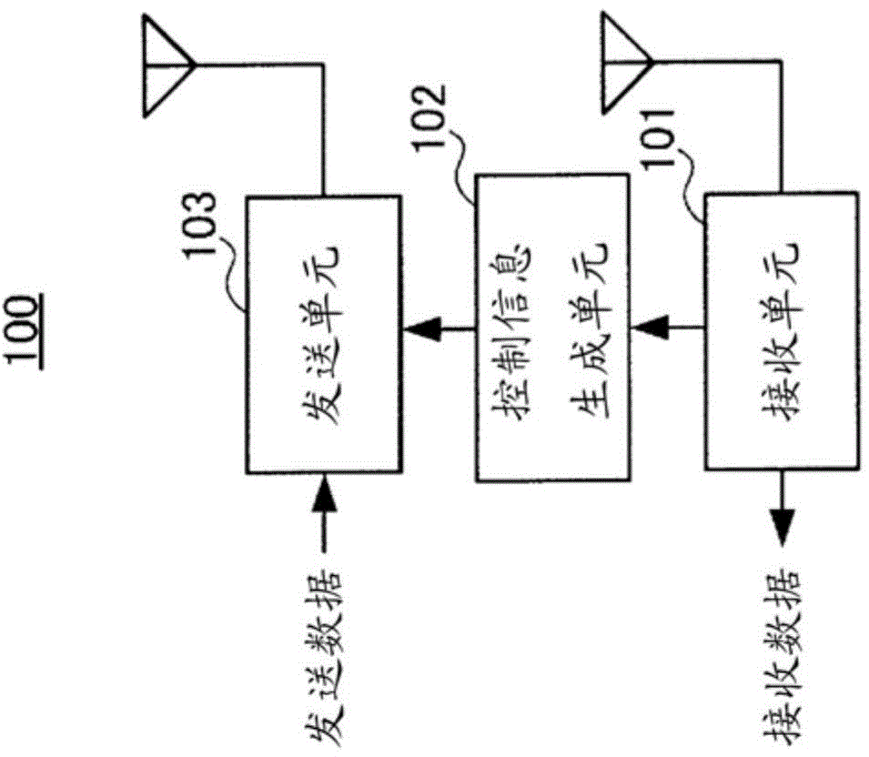
[0062] figure 1 It is a block diagram showing the configuration of a base station according to Embodiment 1 of the present invention. figure 1 The shown base station 100 is mainly composed of a receiving unit 101 , a control information generating unit 102 and a sending unit 103 .

[0063] The receiving unit 101 is for each terminal 200 (refer to figure 2 ) to receive the wireless signal received via the antenna (down-conversion, demodulation, decoding, etc.), and extract PUSCH, PUCCH, SRS, etc. Receiving section 101 outputs the decoded PUSCH data signal as received data. Receiving section 101 outputs the decoded PUCCH control information to control information generating section 102 . Also, receiving section 101 measures the reception timing of a signal transmitted from each terminal for each CC, and outputs information indicating the measurement result to control information generating section 102 .

[0064] The control information ...

specific example 1

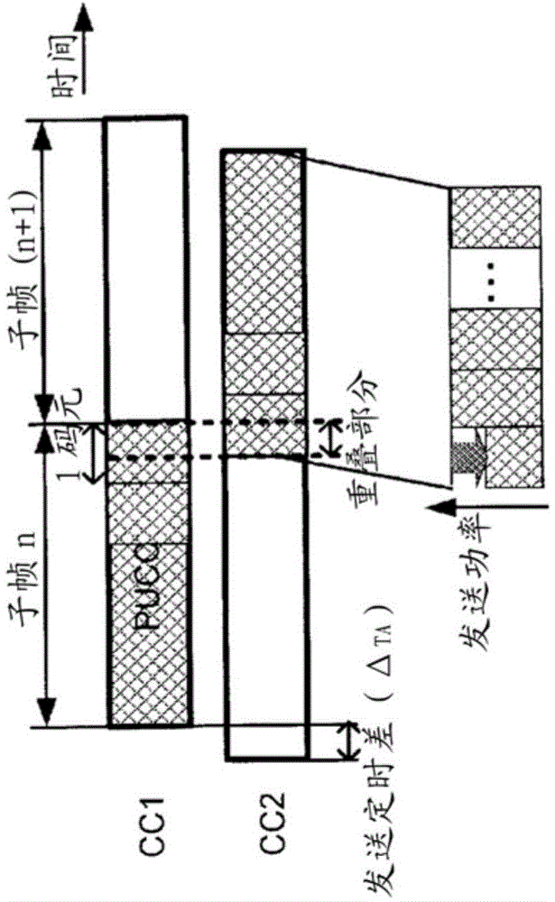
[0083] image 3It is a diagram showing a first example for explaining the transmission power control method of this embodiment. image 3 This is an example of a case where a PUCCH with high priority is transmitted using subframe n of CC1, a PUSCH with low priority is transmitted using subframe (n+1) of CC2, and the transmission timing of CC2 is earlier than the transmission timing of CC1. also, image 3 , assuming that the timing difference between CC1 and CC2 is Δ TA .

[0084] In this case, the end of the PUCCH in subframe n overlaps with the beginning of the PUSCH in subframe (n+1). When the total value of the transmission power exceeds the allowable value in the overlapping portion, the terminal 200 reduces the entire PUSCH symbol (the first symbol of the subframe (n+1)) including the portion where the total value of the transmission power exceeds the allowable value. the sending power.

specific example 2

[0086] Figure 4 It is a diagram showing a second example for explaining the transmission power control method of this embodiment. Figure 4 This is an example of a case where a high-priority PUCCH is transmitted using subframe (n+1) of CC1, a low-priority PUSCH is transmitted using subframe n of CC2, and the transmission timing of CC2 is later than the transmission timing of CC1. also, Figure 4 , assuming that the timing difference between CC1 and CC2 is Δ TA .

[0087] In this case, the end of the PUSCH in subframe n overlaps with the beginning of the PUCCH in subframe (n+1). When the total value of transmission power exceeds the allowable value in the overlapping portion, terminal 200 reduces the transmit power of the entire PUSCH symbol (the last symbol of subframe n) including the portion where the total value of transmission power exceeds the allowable value.


PUM


Abstract

The present invention prevents an increased error rate, degradation of reception-quality estimation precision, and complication of control in an operation for independently controlling, for individual component carriers (CC), transmission timing of an uplink subframe. When a wireless communication terminal device independently controls the subframe transmission timing for individual CCs, and a portion of the total transmission power where overlap exists between the trailing-end portion of a subframe of a CC and a leading-end portion of a subframe of another CC exceeds a tolerance, the terminal device controls the timing such that the transmission power of a symbol including the overlapping portion is reduced.

Description

technical field [0001] The present invention relates to a wireless communication terminal device and a transmission power control method of a mobile communication system that controls the transmission timing of an uplink subframe for each CC (Component Carrier). Background technique [0002] In 3GPP (3rd Generation Partnership Project: 3rd Generation Partnership Project), in order to achieve high-speed, large In the communication of capacity, LTE (Long Term Evolution: Long Term Evolution) and LTE-Advanced (LTE-Advanced) are standardized, and standardization work for further progress (function enhancement) is currently underway. [0003] In LTE and Advanced LTE, OFDMA (Orthogonal Frequency Division Multiple Access: Orthogonal Frequency Division Multiple Access) is used as the downlink communication method, and SC-FDMA (Single Carrier Frequency Division Multiple Access: Single Carrier Frequency Division Multiple Access) is used as the communication method. Uplink communicatio...

Claims


Application Information

Patent Timeline
IPC IPC(8): H04W52/34H04B1/04H04J11/00H04W72/04
CPCH04L5/001H04W72/0446H04W52/367H04W52/30H04L5/0064
Inventor 西尾昭彦铃木秀俊
Owner PANASONIC INTELLECTUAL PROPERTY CORP OF AMERICA
Why Eureka
Try Eureka