Digital radio communications method using multi-level modulation scheme and transmitter and receiver

a multi-level modulation and digital radio technology, applied in the field of digital radio communications system, can solve the problems that such signal point arrangement at equal intervals is not necessarily optimal in terms of error rate, and bit correction processing cannot be said to be necessarily optimal, so as to improve the error rate improve the error rate, and improve the effect of multi-level modulation schem

Inactive Publication Date: 2009-06-25
FUJITSU LTD
View PDF7 Cites 52 Cited by
  • Summary
  • Abstract
  • Description
  • Claims
  • Application Information

AI Technical Summary

Benefits of technology

[0068](26) As still another preferred aspect, the symbol arrangement controlling means may control the symbol arrangement in a direction such that a transmission power is not changed before and after the change of the symbol arrangement.
[0075]The above described aspect realizes at least any one of the following effects and benefits.
[0076](1) Since symbol arrangement is controlled to be changed from an equal interval arrangement to another arrangement in accordance with a ratio (for example, changes in accordance with a coding ratio) of codes different in significance obtained as a result of coding a information series to be transmitted, it is possible to make a code of high significance (or a code of low significance) resistant to an error. In consequence, the effect of bit correction processing can be exhibited sufficiently, so that an error rate of the multi-level modulation scheme is improved.
[0077](2) Further, when a transmission electric power is made not to be changed before and after the change of symbol arrangement, it is possible to moderate increase in load (e.g. required amplification characteristic) due to average transmission power increase accompanying change of symbol arrangement in a transmitter.
[0078](3) Furthermore, to control the bit arrangement in such a manner that a ratio of multiple types of codes low in significance, of the above mentioned multiple codes, becomes equal for each of the multiple bits in the bit correction process, contributes to further improvement of an error rate.

Problems solved by technology

However, in a case in which the above described turbo coding and bit correction processing are used in combination, it cannot be said that such signal point arrangement at equal intervals are necessarily optimal in terms of an error rate.
In addition, bit correction processing cannot be said to be necessarily optimal.

Method used


Image

  • Digital radio communications method using multi-level modulation scheme and transmitter and receiver
  • Digital radio communications method using multi-level modulation scheme and transmitter and receiver
  • Digital radio communications method using multi-level modulation scheme and transmitter and receiver

Examples


first embodiment

[2] First Embodiment

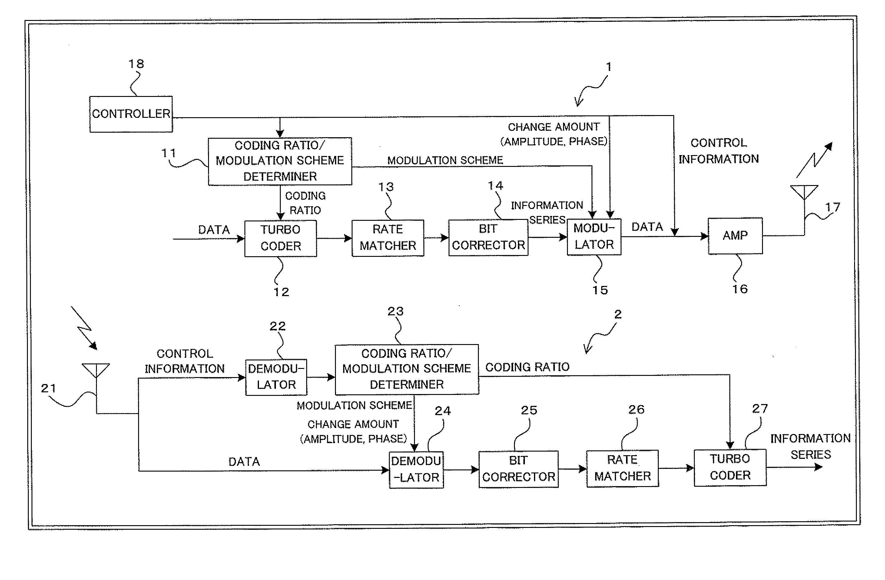
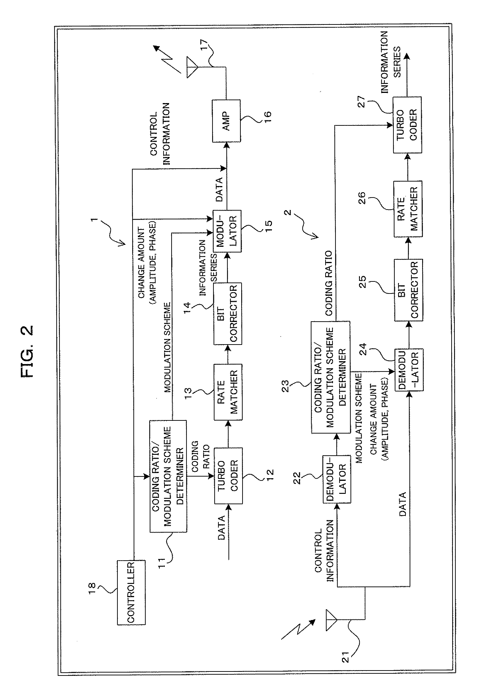
[0149]FIG. 2 is a block diagram illustrating a construction of a digital radio communication system using turbo coding and bit correction according to a first embodiment of the present invention. The digital radio communications system of FIG. 2 includes a transmitter 1 and a receiver 2. The transmitter 1 is applicable, for example, to a radio base transceiving station (BTS); the receiver 2 is applicable, for example, to a mobile station (MS).

[0150]Then, with attention paid to important parts thereof, the transmitter 1 includes, for example: a coding ratio / modulation scheme determiner 11; a turbo coder 12; a rate matcher 13; a bit corrector 14; a modulator 15; an amplifier (AMP) 16; a transmitter antenna 17; and a controller 18. The receiver 2 includes, for example: a receiver antenna 21; a demodulator 22; a coding ratio / modulation scheme determiner 23; a demodulator 24; a bit corrector 25; a rate matcher 26; and a turbo decoder 27. In this instance, the turbo co...

second embodiment

[3] Second Embodiment

[0256]FIG. 34 is a block diagram illustrating a construction of a digital radio communications system using turbo coding and bit correction according to a second embodiment. As in the case of the first embodiment, the digital radio communications system shown in FIG. 34 includes a transmitter 1 and a receiver 2. The transmitter 1 is applicable to, for example, a radio base transceiving station (BTS); the receiver 2 is applicable to, for example, a mobile station (MS). The second embodiment differs from the construction shown in FIG. 2 in that an amplitude / angle calculator 19 is added to the transmitter 1 and that the amplitude / angle calculator 28 is added to the receiver 2. In this instance, elements with reference characters the same as those already described are the same as or similar to the elements already described.

[0257]Here, as shown in FIG. 35, for example, the amplitude / angle calculator (symbol control amount calculating unit) 19 of the transmitter 1 s...


PUM


Abstract

A transmitter for use in digital radio communications systems includes: a bit corrector controls bit arrangement in such a manner that a code having high significance, out of multiple codes obtained by coding, is allocated with high priority to a bit having a tendency that the likelihood enlarges at the time of symbol decision on a receiver; a multi-level modulator allocates the code to the multiple bits in accordance with a predetermined symbol arrangement; and a symbol arrangement controller controls the symbol arrangement from equal distance arrangement to another arrangement in accordance with a ratio of the codes different in significance. To control symbol arrangement increases the effect of bit correction and improves an error rate on the receiver.

Description

[0001]This application is a continuation of International Application No. PCT / JP05 / 023956, filed Dec. 27, 2005, now pending, the contents of which are incorporated by reference.TECHNICAL FIELD[0002]The present invention relates to a digital radio communications system employing the multi-level modulation scheme and also to a transmitter and a receiver. The invention relates, for example, to the technology suitable for use in a digital radio communications system using bit correction processing.BACKGROUND ART[0003]Recent digital radio communications systems employ the multi-level modulation scheme such as QPSK (Quadrature Phase Shift Keying), 8PSK, and 16QAM (Quadrature Amplitude Modulation) in order to enable high-speed transmission while effectively using limited radio frequency bands. That is, QPSK is capable of transmitting two bits by a single symbol; 8PSK is capable of transmitting three bits by a single symbol; 16QAM is capable of transmitting four bits by a single symbol. In ...

Claims


Application Information

Patent Timeline
Patent Type & Authority Applications(United States)
IPC IPC(8): H04L25/34
CPCH03M13/256H03M13/258H03M13/2957H03M13/2966H04L2001/0098H04L1/0041H04L1/006H04L1/0064H04L27/34H03M13/356
Inventor NAKAGAWA, TAKAOYANO, TETSUYAOBUCHI, KAZUHISA
Owner FUJITSU LTD
Why Eureka
Try Eureka