
Forming machine for foaming polyphenyl sandwich composite thermal-insulation building block subjected to molding at later stage
A block forming machine and composite thermal insulation technology, applied in the field of machinery, can solve problems such as low production efficiency, failure to achieve factory production, and low degree of mechanization, and achieve the effects of improving production efficiency, ensuring quality, and reducing product costs
- Summary
- Abstract
- Description
- Claims
- Application Information
AI Technical Summary
Problems solved by technology
Method used
Image

Examples
Embodiment Construction
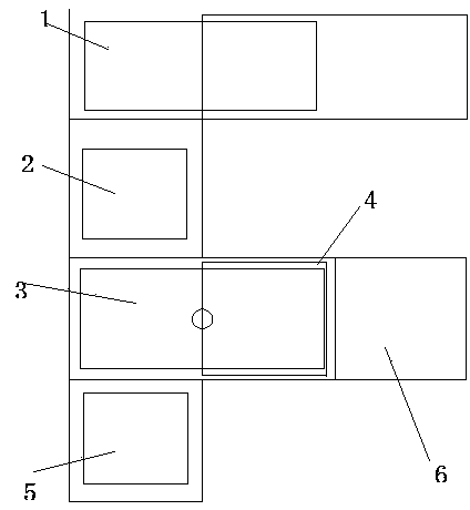
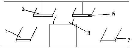
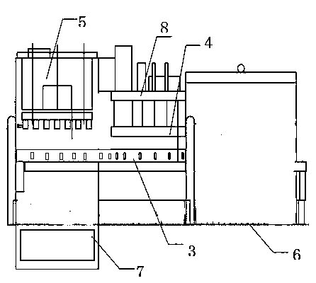
[0021] A post-molding foamed polystyrene sandwich composite thermal insulation block molding machine, including a frame, characterized in that it also includes an automatic loading and unloading machine 1, the frame is a "T"-shaped structure, mainly composed of gantry Type clamp 2, rotatable mold turn 3, upper mold 4, block forming device 8, and gantry mechanical stripper 5.
[0022] One end of the "T"-shaped frame is provided with a gantry clamp 2 which can move left and right and up and down, and the other end is provided with a gantry mechanical stripper 5 which can move left and right and up and down. A rotatable mold 3 is arranged at the junction of the "T" shape. The rotatable mold 3 is composed of two sub-moulds that can correspond to the upper mold 4 respectively. The center position of the two sub-moulds is the center of rotation 9. Go up and arrange upper mold 4 and block forming device 8, " T " font lower position arranges braking system.
[0023] The described aut...
PUM
 Abstract
Description
Claims
Application Information