
Layout scheme and control method of tilt rotor transport aircraft

A tilt-rotor and transport aircraft technology, applied in the aviation field, can solve the problems of reducing the lift-drag ratio and cruising efficiency of the aircraft, the mutual interference between the rotor and the wing, and the influence of the level flight performance, so as to improve the hovering efficiency and flight reliability, High cruising efficiency and good adaptability

Inactive Publication Date: 2014-10-08
SHANGHAI DONGGU AVIATION TECH CO LTD
View PDF8 Cites 20 Cited by
  • Summary
  • Abstract
  • Description
  • Claims
  • Application Information

AI Technical Summary

Problems solved by technology

This layout method can also realize vertical take-off and landing and change from hovering to level flight, but one point that cannot be ignored is that this layout method actually causes damage to the wing surface, reducing the lift-to-drag ratio and cruise efficiency of the aircraft. Level flight performance is greatly affected
[0006] "Flight Mechanics" in February 2010, Volume 28, Issue 1, published by Zou Candong, Qu Xiangju and Wang Weijun in the article "Modeling and Experiments of Tilter Rotor Hovering" also proposed an overall layout of the tilt rotor aircraft. The layout scheme, in which the engine and the rotor are still arranged at both ends of the wing, and the third auxiliary rotor is arranged at the nose, this scheme still fails to solve the problem of mutual interference between the rotor and the wing in the hovering state

Method used


Image

  • Layout scheme and control method of tilt rotor transport aircraft
  • Layout scheme and control method of tilt rotor transport aircraft
  • Layout scheme and control method of tilt rotor transport aircraft

Examples


Embodiment Construction

[0040] The present invention is described in further detail now in conjunction with accompanying drawing. These drawings are all simplified schematic diagrams, which only illustrate the basic structure of the present invention in a schematic manner, so they only show the configurations related to the present invention.

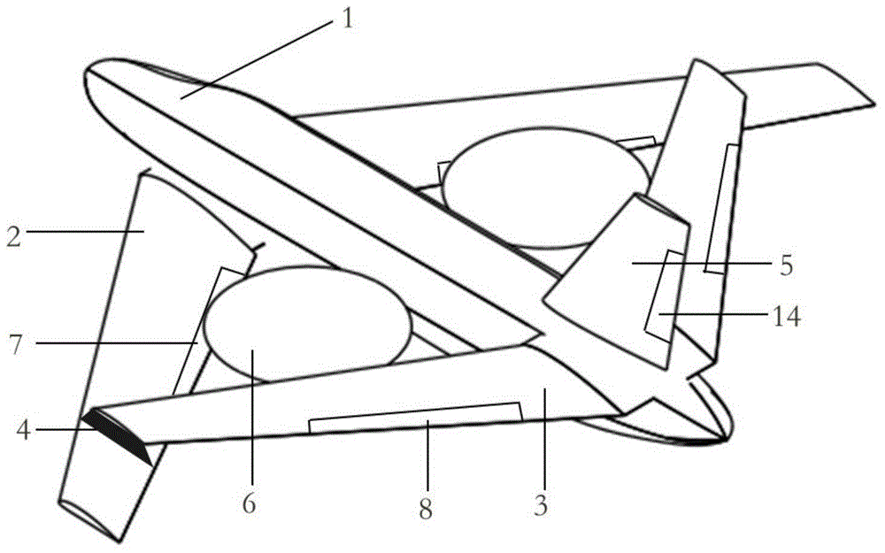
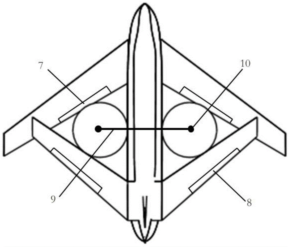
[0041] Such as Figure 1 ~ Figure 4 As shown, the layout scheme of a new type of tilt-rotor transport aircraft includes fuselage 1, front wing 2, rear wing 3, front and rear wing connecting end plates 4, vertical tail 5, rotor 6, front wing aileron 7 , rear wing aileron 8, tiltable main shaft 9, engine 10, engine small-angle turning mechanism 11, slipstream rudder 12, slipstream rudder rudder surface 13, rudder 14.

[0042] The fuselage 1 is the main load-carrying part of the transport aircraft, and also plays the role of connecting various parts; the front wing 2 and the rear wing 3 are used to provide lift in level flight, and the front wing aileron 7 and t...


PUM


Abstract

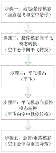
The invention relates to a layout scheme of a tilt rotor transport aircraft. According to the layout scheme, the tilt rotor transport aircraft comprises a body, front wings, rear wings, front-rear-wing connecting end plates, a vertical tail wing, rotor wings, front wing auxiliary wings, rear wing auxiliary wings, a rotatable main shaft, engines, engine small-angle rotating mechanisms, a slip-flow rudder, a slip-flow rudder surface and a rudder; the body is connected with the front wings, the rear wings, the rotatable main shaft and the vertical tail wing; the front wings and the rear wings are arranged on the front end and the rear end of the body, and the front wing auxiliary wings and the rear wing auxiliary wings are respectively installed on the front wings and the rear wings; the vertical tail wing is installed on the tail end of the body, the rudder is installed on the vertical tail wing, and the rotatable main shaft is connected with the engine small-angle rotating mechanism in a rotating manner; the rotor wing is installed on an output shaft of the engine; the slip-flow rudder is installed on the rotatable main shaft, and the slip-flow rudder surface is installed on the slip-flow rudder. The invention relates to a control method of the tilt rotor transport aircraft. The control method comprises five steps. By adopting the layout and the control method of the tilt rotor transport aircraft, the pneumatic interference and mode transformation between the rotor wings and the wings of the aircraft can be solved, the transport capacity and the vertical take-off and landing capacity of the connected-wing layout can be reasonably combined, and a novel type of transport aircraft is formed.

Description

technical field [0001] The invention relates to a layout scheme of a tiltrotor transport aircraft and a control method thereof, which is a layout scheme of a vertical take-off and landing transport aircraft based on the tilt rotor technology and its operation in vertical take-off and landing, hovering, and level flight modes. and the control method for switching between modes. It belongs to the field of aviation technology. technical background [0002] Giving aircraft vertical take-off and landing capabilities has always been the dream of aviation engineers. After decades of exploration and development, vertical take-off and landing aircraft are divided into three directions: one is based on the "Harrier" fighter and the F-35 "Lightning" The scheme represented by tilting the engine nozzle to obtain vector thrust to achieve vertical take-off and landing is generally applicable to fighter jets requiring high maneuverability; one is the so-called "rotor-fixed-wing compound hi...

Claims


Application Information

Patent Timeline
Patent Type & Authority Applications(China)
IPC IPC(8): B64C27/22B64C27/52B64C29/02B64C3/38
Inventor 周尧明于沿蒙志君何维陈旭智
Owner SHANGHAI DONGGU AVIATION TECH CO LTD
Learn More