
Remote sensing unmanned aerial vehicle frame

An airframe, remote sensing technology, applied in aircraft parts, transportation and packaging, etc., can solve the problems of single shooting angle, single shooting angle, low shooting efficiency, etc., and achieve the effect of many installation locations and regular distribution areas.

Active Publication Date: 2014-10-08
JIAXING ANXING INFORMATION TECH
View PDF5 Cites 2 Cited by
  • Summary
  • Abstract
  • Description
  • Claims
  • Application Information

AI Technical Summary

Problems solved by technology

[0002] The existing aerial photography support has a simple structure and a single installation accessory. Generally, only one video camera or camera can be installed, and it is difficult to complete the installation of other auxiliary equipment.
Moreover, the shooting angle is single, and the shooting angle can only be changed simply by relying on the steering of the remote sensing drone
The aerial photography effect of the remote sensing UAV can not achieve the expected effect in the end, the shooting angle is single, and repeated shooting is required many times, the shooting efficiency is low, and the time is wasted for a long time

Method used


Image

  • Remote sensing unmanned aerial vehicle frame
  • Remote sensing unmanned aerial vehicle frame
  • Remote sensing unmanned aerial vehicle frame

Examples


Embodiment Construction

[0011] The present invention will be further described below in conjunction with drawings and embodiments.

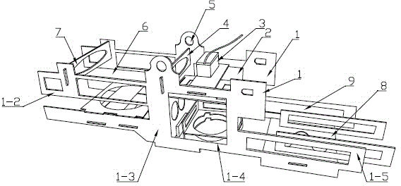
[0012] Such as figure 1 As shown, the present invention includes two main side plates 1 , a first connection support plate 7 , a second connection support plate 4 and a third connection support plate 8 . The first connection support plate 7 , the second connection support plate 4 and the third connection support plate 8 are clamped between the two main side plates 1 . Between the first connection support plate 7 and the second connection support plate 4 is the first installation area 6; between the second connection support plate 4 and the third connection support plate 8 is the second installation area 2; the third connection support plate 8 For the third installation area 9.

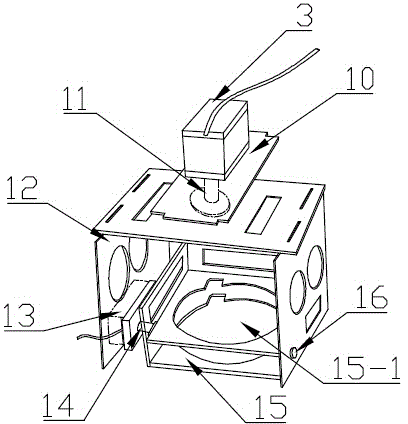
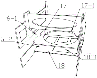
[0013] Such as figure 2 As shown, the second installation area 2 is provided with a horizontal plate 10 clamped to the two main side plates 1, the first motor 3 is installed on the horizonta...


PUM


Abstract

The invention discloses a remote sensing unmanned aerial vehicle frame which comprises two main lateral plates, a first connection support plate, a second connection support plate and a third connection support plate. A first installation area is formed between the first connection support plate and the second connection support plate. A second installation area is formed between the second connection support plate and the third connection support plate. The third connection support plate is a third installation area. A horizontal plate clamped onto the two main lateral plates is arranged on the second installation area, a first motor is installed on the horizontal plate, a video camera / camera installation frame is arranged below the horizontal plate and comprises a rotating frame and an overturning frame, the overturning frame is located in the rotating frame, the rotating frame is fixedly connected with a rotating shaft on the first motor, a second motor is installed on the side of the rotating frame, one end of the overturning frame is fixedly connected with a rotating shaft on the second motor, and the other end of the overturning frame is connected with the rotating frame through a bolt. The remote sensing unmanned aerial vehicle frame can achieve multi-angle flexible camera shooting, achieves installation of various auxiliary devices and provides guarantee for the shooting process.

Description

technical field [0001] The invention relates to a bracket installed on a remote sensing drone, in particular to a remote sensing drone frame. Background technique [0002] The existing aerial photography support has a simple structure and a single installation accessory. Generally, only one video camera or camera can be installed, and it is difficult to complete the installation for other auxiliary equipment. Moreover, the shooting angle is single, and the shooting angle can only be changed simply by relying on the steering of the remote sensing drone. The aerial photography effect of the remote sensing UAV can not achieve the expected effect in the end, the shooting angle is single, and repeated shooting is required many times, the shooting efficiency is low, and the time is wasted for a long time. Contents of the invention [0003] The purpose of the present invention is to provide a remote sensing drone. [0004] The present invention solves the problem that the exis...

Claims


Application Information

Patent Timeline
IPC IPC(8): B64D47/08
Inventor 李东亮
Owner JIAXING ANXING INFORMATION TECH
Learn More