Device for testing loading of component compositely stressed by pressure, bending moment and shearing force

A loading test device and composite force-bearing component technology, applied in the direction of testing material strength by applying stable bending force, testing material strength by applying stable shear force, testing material strength by applying stable tension/compression, etc., can Solve the problems of high requirements for reaction frame, unfavorable in-depth research and engineering application of bending and shearing components, complex structure, etc., and achieve the effect of low requirements, high recycling value and simple structure of the device

Inactive Publication Date: 2014-10-08
EAST CHINA JIAOTONG UNIVERSITY
View PDF4 Cites 27 Cited by
  • Summary
  • Abstract
  • Description
  • Claims
  • Application Information

AI Technical Summary

Problems solved by technology

At present, the domestic loading test devices for compression-bending-shear members mainly include MTS actuators, hydraulic jack...

Method used


Image

  • Device for testing loading of component compositely stressed by pressure, bending moment and shearing force
  • Device for testing loading of component compositely stressed by pressure, bending moment and shearing force

Examples


Embodiment Construction

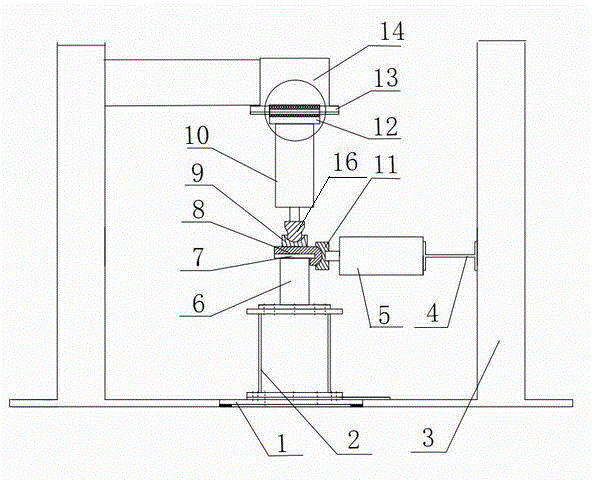
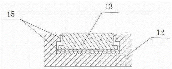
[0008] A loading test device for a compression-bending-shear composite stressed member, comprising a bottom fixed base 1, a base box 2, a reaction force frame 3, a horizontal jack 5, a vertical jack 10, and a top beam 14, and the bottom fixed base 1 is fixed on In the center of the bottom plate of the reaction force 3 frame, the base box 2 is installed on the bottom fixed base 1. It is characterized in that the bottom end of the test piece 6 is fixed on the base box 2 by bolts, and the horizontal jack 5 is installed on the I-shaped steel by bolts. 4, the I-shaped steel 4 is fixed on the side of the reaction force frame 3, the vertical jack 10 is fixed on the support frame 12, and the support frame 12 is sleeved in the slide rail 13 on the top beam 14 of the reaction force frame 3, and the support frame 12 and Balls 15 are installed between the slide rails 13; a horizontal loading arc hinge 11 is fixed on the top shaft of the horizontal jack 5, and a concave arc groove is opened...


PUM


Abstract

The invention discloses a device for testing loading of a component compositely stressed by pressure, bending moment and shearing force. The bottom end of a test piece is fixed on a base box; a horizontal jack is fixed on a reaction frame; a vertical jack is fixed on a support frame; the support frame is arranged in a sliding rail of a top beam of the reaction frame in a sleeving manner; a transverse loading arc hinge is arranged on a jacking shaft of the horizontal jack; a transverse loading plate is arranged on a cover plate of the test piece; a jacking shaft of the vertical jack is fixedly connected with a vertical loading ball hinge; the bottom surface of the vertical loading ball hinge is a spherical surface; a spherical groove is formed in a vertical loading ball base; the spherical groove is matched with the spherical surface of the bottom of the vertical loading ball hinge so as to form an arc hinge. By virtue of the device for testing the loading of the component, loading of various components in the presence of pressure, bending moment and shearing force can be achieved; the arc hinge formed by the transverse loading plate and the transverse loading hinge can be used for applying horizontal shearing force; the ball hinge formed by the vertical loading ball hinge and the vertical loading ball base can be used for applying axial pressure. The device with the structure ensures that the overall horizontal shearing force is born by the test piece; the overall device is relatively simple in structure and reliable to use.

Description

technical field [0001] The invention relates to a loading test device for a compression-bending-shear composite stress member. Background technique [0002] Architectural components are used in practical engineering, such as joints with diagonal braces between steel pipe concrete columns, joints between original buildings and building extensions, beam-column joints of long-span heavy-duty beams, these places may have impacts Shear problems of building elements with their bearing capacity. The seismic investigation and observation found that the failure of the columns in the building structure is caused by different combinations of compression-bending-shear-torsional composite loads. At present, the domestic loading test devices for compression-bending-shear members mainly include MTS actuators, hydraulic jacks, reaction steel frames, and reaction steel columns. In-depth research and engineering application of compression-bending-shear members. Therefore, a simple and econ...

Claims


Application Information

Patent Timeline
IPC IPC(8): G01N3/08G01N3/20G01N3/24
Inventor 黄宏陈梦成林博洋许开成袁方曾根平
Owner EAST CHINA JIAOTONG UNIVERSITY
Why Eureka
Try Eureka